
Lobe-shaped backward step structure, lobe-shaped concave cavity device and afterburning chamber

A supplementary combustion chamber and wave lobe technology, which is applied in the direction of combustion chamber, continuous combustion chamber, combustion method, etc., can solve the problems of slow development of shear layer, small flame propagation range, poor air mixing effect, etc.

Active Publication Date: 2021-05-04
NAT UNIV OF DEFENSE TECH
View PDF10 Cites 7 Cited by
  • Summary
  • Abstract
  • Description
  • Claims
  • Application Information

AI Technical Summary

Problems solved by technology

However, for solid rocket scramjet engines, mixing has a greater impact on its performance. Due to the compressibility of supersonic airflow, the shear layer of the device develops slowly. Therefore, the traditional concave cavity flame stabilizer has poor airflow mixing effect. , the problem of small flame spread range

Method used


Image

  • Lobe-shaped backward step structure, lobe-shaped concave cavity device and afterburning chamber
  • Lobe-shaped backward step structure, lobe-shaped concave cavity device and afterburning chamber
  • Lobe-shaped backward step structure, lobe-shaped concave cavity device and afterburning chamber

Examples


Embodiment Construction

[0037] The following will clearly and completely describe the technical solutions in the embodiments of the present invention with reference to the accompanying drawings in the embodiments of the present invention. Obviously, the described embodiments are only part of the embodiments of the present invention, not all of them. Based on the embodiments of the present invention, all other embodiments obtained by persons of ordinary skill in the art without creative efforts fall within the protection scope of the present invention.

[0038]It should be noted that all directional indications (such as up, down, left, right, front, back...) in the embodiments of the present invention are only used to explain the relationship between the components in a certain posture (as shown in the accompanying drawings). Relative positional relationship, movement conditions, etc., if the specific posture changes, the directional indication will also change accordingly.

[0039] In addition, in th...


PUM


Abstract

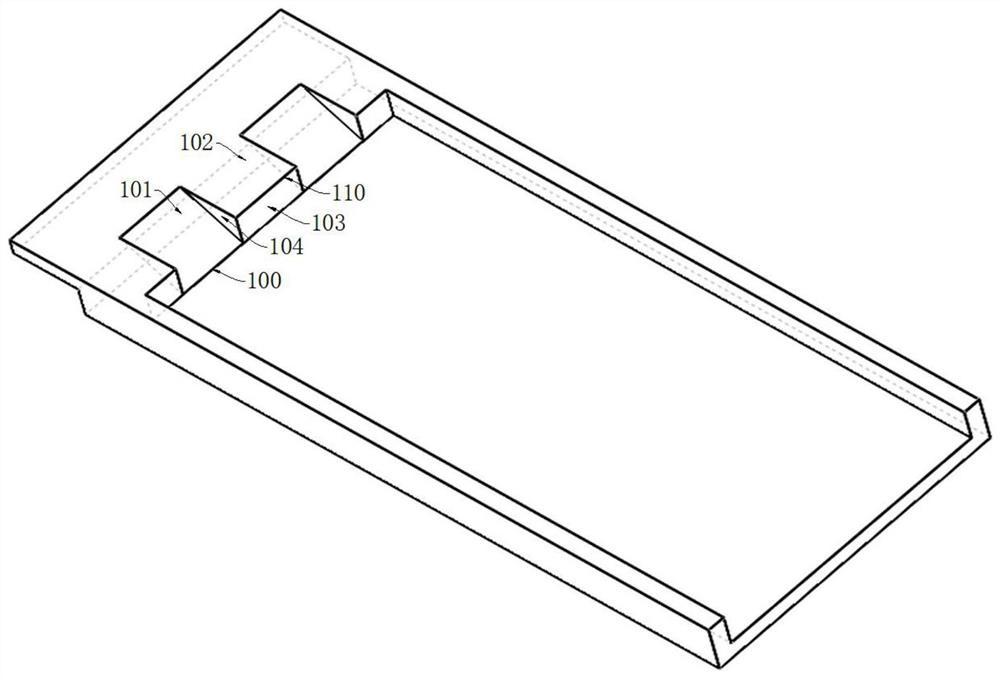
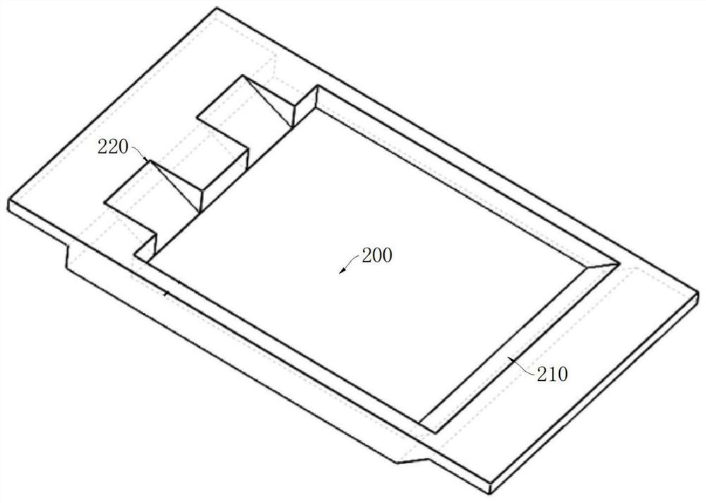
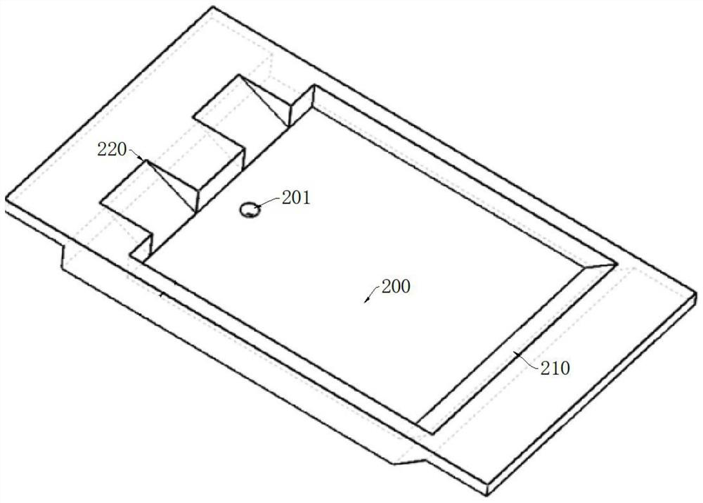
The invention discloses a lobe-shaped backward step structure, a lobe-shaped concave cavity device and an afterburning chamber. The lobe-shaped concave cavity device is a constituent part of the wall face of a solid rocket excess combustion ramjet engine. The lobe-shaped backward step structure comprises a plurality of lobe grooves and backward steps which are distributed in a staggered mode in the spanwise direction of the wall face of the solid rocket excess combustion ramjet engine. The lobe-shaped concave cavity device comprises a concave cavity, a forward step and the lobe-shaped backward step structure. The lobe-shaped backward step structure is arranged at the end, located at the upstream end of the airflow in the engine, of the concave cavity, and the forward step is arranged at the end, located at the downstream end of the airflow in the engine, of the concave cavity. By the adoption of the lobe-shaped cavity device, flames can be effectively stabilized, mixed combustion of rich combustion gas and incoming flow air in the afterburning chamber is enhanced, and meanwhile the lobe-shaped cavity device is simple in structure and suitable for the solid rocket excess combustion ramjet engine.

Description

technical field [0001] The invention relates to the technical field of solid rocket scramjet, in particular to a lobe-type backward step structure, a lobe-type concave cavity device and a supplementary combustion chamber. Background technique [0002] The solid rocket scramjet uses the fuel-rich gas produced by the gas generator to mix and burn with air to produce high-temperature gas, which is then expanded by the nozzle to generate thrust. Compared with liquid scramjet, it has the advantages of simple structure, low cost, short combat response time, good maneuverability and safety, and long storage time. Compared with solid fuel scramjet, it has the advantages of easy flow adjustment and no ignition The flame stability problem, the working process of the combustion chamber is less affected by the flow parameters, and the working time is long. Therefore, the solid rocket scramjet has a good application prospect. [0003] At present, the research on solid rocket scramjet at...

Claims


Application Information

Patent Timeline
IPC IPC(8): F23R3/58
CPCF23R3/58
Inventor 杨鹏年马立坤夏智勋陈斌斌冯云超赵翔李潮隆赵李北
Owner NAT UNIV OF DEFENSE TECH
Learn More