Supercharge Your Innovation With Domain-Expert AI Agents!

Power system low-frequency oscillation mode identification method based on LSTM and phase trajectory

A low-frequency oscillation, power system technology, applied in the direction of reducing/preventing power oscillation, electrical components, circuit devices, etc., to achieve accurate and reliable results, simplify the analysis process, and improve the identification speed.

Active Publication Date: 2021-05-04
UNIV OF ELECTRONICS SCI & TECH OF CHINA
View PDF17 Cites 0 Cited by
  • Summary
  • Abstract
  • Description
  • Claims
  • Application Information

AI Technical Summary

Problems solved by technology

Although many improvements have been made to address the shortcomings of these classic methods, it is still difficult to fundamentally adapt to the randomness and rapidity of system state changes in a power system with a high proportion of renewable energy connected to the grid.

Method used


Image

  • Power system low-frequency oscillation mode identification method based on LSTM and phase trajectory
  • Power system low-frequency oscillation mode identification method based on LSTM and phase trajectory
  • Power system low-frequency oscillation mode identification method based on LSTM and phase trajectory

Examples


Embodiment 1

[0140] In order to verify whether the algorithm can identify new oscillation modes superimposed in the oscillation process of the system, the ideal LFO test signal is constructed as follows:

[0141]

[0142] In formula (16), ε(t) represents a step function, and η(t) represents a noise signal.

[0143] Such as Figure 5 As shown, the length of the LFO signal is 12s, and the signal-to-noise ratio SNR=10dB. Before 6s, the signal contains two modes, where the frequency f 1 = 0.77Hz, f 2 =1.15Hz, attenuation factor σ 1 =0.12, σ 2 =-0.32. When t=6s, a new oscillation mode is introduced, its frequency f 3 =1.98Hz, attenuation factor σ 3 =0.08. After 6s, due to the σ in the initial mode 2 =-0.32 belongs to the strong attenuation component, at this time the mode is no longer counted as the dominant mode, so the signal still contains two modes, where the frequency f 1 = 0.77Hz, f 3 =1.98Hz, attenuation factor σ 1 =0.12, σ 2 = 0.08.

[0144] Step 7: Obtain the measured d...

Embodiment 2

[0150] In order to verify the actual identification effect of the present invention, a piece of LFO measured data is obtained from the power system. Such as Figure 6 As shown, the LFO signal in this segment is excited by two small disturbances, located at 4s and 7s respectively, both lasting 0.1s. In order to identify the mode of the LFO excited by the two disturbances, the data after the disturbance is intercepted as the LFO signal to be tested in this embodiment.

[0151] Step 7: Obtain the measured data of the LFO signal through the sliding time window. The sliding window length is 5s, the sliding interval is 1s, and the sampling frequency is 100Hz. In order to verify the applicability of the present invention in the case of multiple disturbances in the system, it is necessary to use sliding window sampling after two disturbances occur. In this embodiment, two segments of signals are selected as identification objects, which are 4.1-9.1s and 7.1-12.1s respectively. Amo...


PUM


Abstract

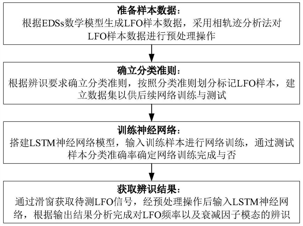
The invention discloses a power system low-frequency oscillation mode rapid identification method based on an LSTM neural network and a phase trajectory analysis method, and provides a power system low-frequency oscillation mode rapid identification method which is accurate in analysis and reasonable in design, and the method comprises the steps: generating LFO sample data according to an EDSs mathematical model, carrying out preprocessing operation on the LFO sample data by adopting a phase trajectory analysis method; determining a classification criterion according to an identification requirement, dividing and marking LFO samples according to the classification criterion, and establishing a data set for subsequent network training and testing; building an LSTM neural network model, inputting a training sample to carry out network training, and determining whether the network training is completed or not through testing sample classification accuracy; and obtaining a to-be-detected LFO signal through a sliding window, inputting the to-be-detected LFO signal into the LSTM neural network after preprocessing operation, and performing analyzing according to an output result to complete identification of the LFO frequency and the attenuation factor mode. The method has the advantages that the low-frequency oscillation mode of the power system can be quickly identified, the change of the low-frequency oscillation mode can be identified, and the reliability of the identification result is high.

Description

technical field [0001] The present invention relates to the technical field of power system stability and control, in particular to a fast detection of low frequency oscillation (LFO) modes of power systems based on long-short-term memory (LSTM) neural network and phase trajectory analysis. identification method. Background technique [0002] In recent decades, in order to alleviate energy shortage and environmental crisis, renewable energy distributed generation technology is booming. Power electronic conversion devices are widely used in distributed power generation. A large number of new energy grid-connected power generation equipment is connected to the grid through power electronic conversion devices. However, these power electronic conversion devices have extremely high response speed and flexible control strategy, and their different dynamic characteristics make the system very prone to oscillation, which brings great challenges to the operation, management and plan...

Claims


Application Information

Patent Timeline
IPC IPC(8): H02J3/24
CPCH02J3/241H02J2203/20
Inventor 张昌华徐子豪张坤吴云峰陈树恒刘群英
Owner UNIV OF ELECTRONICS SCI & TECH OF CHINA
Features
  • R&D
  • Intellectual Property
  • Life Sciences
  • Materials
  • Tech Scout
  • Unparalleled Data Quality
  • Higher Quality Content
  • 60% Fewer Hallucinations
Learn More