
Vertical shaft impact crusher

A vertical shaft impact and crusher technology, which is applied in mechanical material recycling, grain processing, plastic recycling, etc., can solve the problems of poor crushing effect, poor material crushing effect, and no screening of materials with different specifications.

Active Publication Date: 2021-05-07
唐山东道实业有限公司
View PDF15 Cites 2 Cited by
  • Summary
  • Abstract
  • Description
  • Claims
  • Application Information

AI Technical Summary

Problems solved by technology

[0006] How to solve the problem of poor crushing effect caused by centrifugal force when the materials are thrown out of the impeller in the existing scheme, and the lack of screening of materials of different specifications, so that the materials of different specifications are subjected to the same impact force, resulting in poor crushing effect The problem

Method used


Image

  • Vertical shaft impact crusher
  • Vertical shaft impact crusher
  • Vertical shaft impact crusher

Examples


Embodiment 1

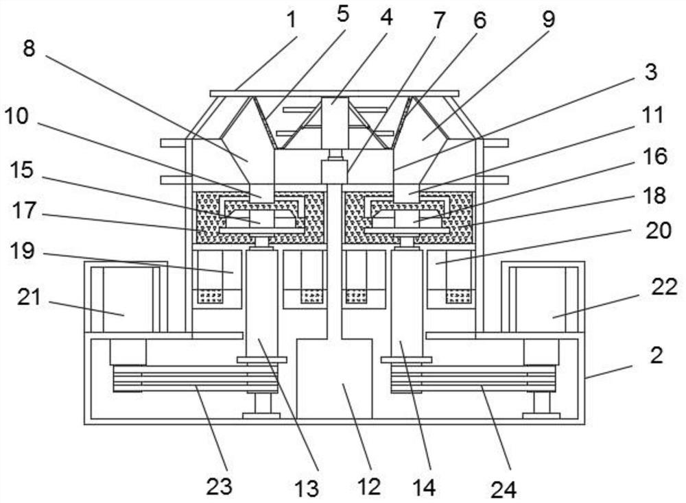
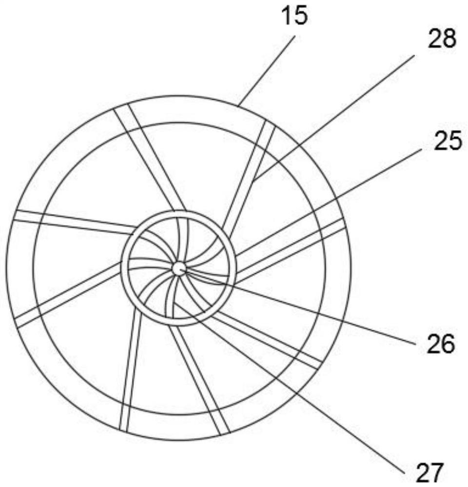
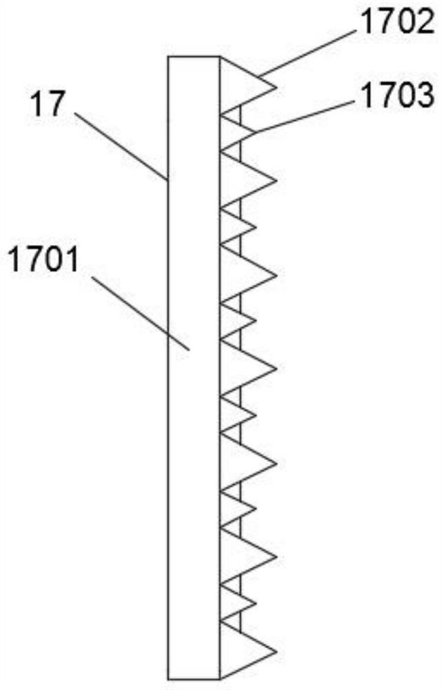
[0038] like Figure 1-7 As shown, a vertical shaft impact crusher includes a crusher body 1, a base 2, a stirring mechanism 4, a first crushing mechanism 17 and a second crushing mechanism 18, and the base 2 is fixedly installed at the lower end of the crusher body 1, A partition plate 12 is fixedly installed in the interior of the base 2 near the middle, the upper end of the partition plate 12 is installed with a support base 3, and the stirring mechanism 4 is installed at the upper end of the support base 3 close to the middle position, so Both sides of the stirring mechanism 4 are slidably connected with a first support plate 35 , the interior of the first support plate 35 is connected with a third support plate 37 at a position close to the bottom, and the first support plate 35 is close to the bottom of the stirring mechanism 4 . A second support plate 36 is fixedly installed on one side, a support transverse plate 30 is fixedly installed in the interior of the stirring m...

Embodiment 2

[0050] The working method of the vertical shaft impact crusher includes the following steps:

[0051] Step 1: The material is transported to the inside of the crusher body 1 through the feeding port, the material enters between the first filter plate 5 and the second filter plate 6, the first drive motor 7 is started, and the first drive motor 7 drives the rotation. The column 401 rotates counterclockwise, and the stirring mechanism 4 is driven to rotate counterclockwise through the rotating column 401;

[0052] Step 2: Activate the air cylinder 31, move the lifting column 33 upward through the air cylinder 31 and the driving column 32, the upward movement of the lifting column 33 drives the slide plate 34 to move upward, the slide plate 34 drives the first support plate 35 to move upward, and the first support plate 35 drives The second support plate 36 moves upward, the first support plate 35 is abutted with the third support plate 37 through the third slider and the slot 42...


PUM


Abstract

The invention discloses a vertical shaft impact crusher. The vertical shaft impact crusher comprises a crusher body, a base, a stirring mechanism, a first crushing mechanism and a second crushing mechanism, the base is fixedly installed at the lower end of the crusher body, a partition plate is fixedly installed at the position, close to the middle, in the base, a supporting seat is installed at the upper end of the partition plate, the stirring mechanism is installed at the position, close to the middle, of the upper end of the supporting seat, first supporting plates are slidably connected to the two sides of the stirring mechanism, third supporting plates are connected to the positions, close to the lower portions, of the interiors of the first supporting plates, and second supporting plates are fixedly installed on the sides, close to the stirring mechanism, of the first supporting plates. According to all aspects disclosed by the invention, the problem that the crushing effect is poor due to the influence of centrifugal force when the materials are thrown out of an impeller can be solved, and the problem that the crushing effect of the materials is poor due to the fact that the materials of different specifications are subjected to the same impact force because the materials of different specifications are not screened can be solved.

Description

technical field [0001] The invention relates to the technical field of crushers, in particular to a vertical shaft impact crusher. Background technique [0002] Impact crusher, referred to as impact crusher, commonly known as sand making machine, is a high-energy and low-consumption impact crusher with international advanced level. Its performance plays an irreplaceable role in various ore fine crushing equipment. Effective, practical and reliable stone crushing machine; it is to let the material collide with the material thrown out by the impeller in the process of natural falling, so as to achieve the purpose of crushing. [0003] Patent Publication No. CN110636905A discloses an impact crusher for mineral materials, comprising: a. a crusher casing; b. a reversible rotor with a horizontal rotating shaft to throw the mineral material into the crusher casing c. drive means to drive the rotor; d. a lower impact grinding chamber, which is defined by at least one impact mechani...

Claims


Application Information

Patent Timeline
Patent Type & Authority Applications(China)
IPC IPC(8): B02C13/18B02C13/20B02C13/282
CPCB02C13/18B02C13/20B02C13/282Y02W30/62
Inventor 吴志朋王明雪
Owner 唐山东道实业有限公司
Learn More