Dispensing needle position calibration system and dispensing needle position calibration method

A technology for calibrating systems and dispensing, applied to spraying devices, devices for coating liquid on surfaces, coatings, etc., can solve problems such as wasting production time

Inactive Publication Date: 2021-05-07
UNITED AUTOMOTIVE ELECTRONICS SYST
View PDF9 Cites 1 Cited by
  • Summary
  • Abstract
  • Description
  • Claims
  • Application Information

AI Technical Summary

Problems solved by technology

Assuming that each production line using a dispensing machine produces more than 14,000 products per day, the calibration is at least 14 times, and at least 28 minutes of production time are wasted

Method used


Image

  • Dispensing needle position calibration system and dispensing needle position calibration method
  • Dispensing needle position calibration system and dispensing needle position calibration method
  • Dispensing needle position calibration system and dispensing needle position calibration method

Examples


no. 1 example

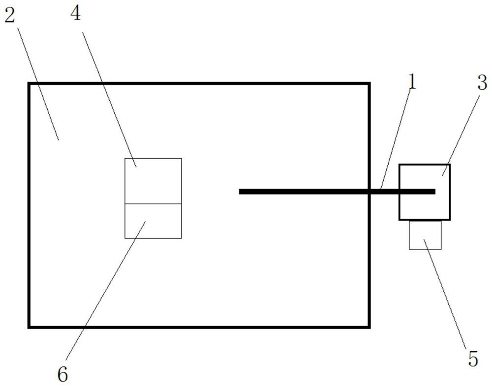
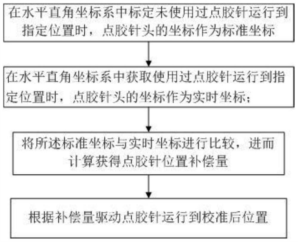
[0054] Such as image 3 As shown, the present invention provides a first embodiment of a dispensing needle position calibration method for dispensing needle position calibration of a dispensing machine, including the following steps:

[0055] 1) When the unused dispensing needle is calibrated to the specified position in the horizontal rectangular coordinate system, the coordinates of the dispensing needle head are taken as the standard coordinates;

[0056] 2) Obtain the coordinates of the dispensing needle as the real-time coordinates when the dispensing needle runs to the specified position in the horizontal rectangular coordinate system;

[0057] 3) Comparing the standard coordinates with the real-time coordinates, and then calculating the position compensation amount of the dispensing needle;

[0058] 4) Drive the dispensing needle to the calibrated position according to the compensation amount.

no. 2 example

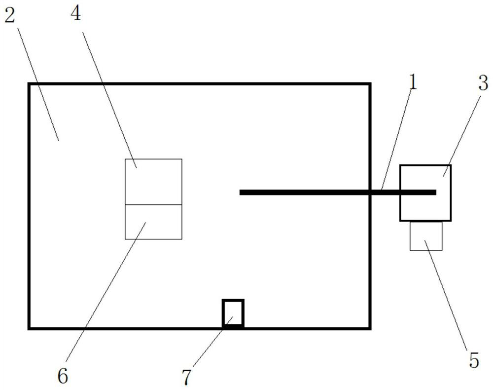
[0059] Such as Figure 4 As shown, the present invention provides a second embodiment of a dispensing needle position calibration method for dispensing needle position calibration of a dispensing machine, including the following steps:

[0060] 1) When the unused dispensing needle is calibrated to the specified position in the horizontal rectangular coordinate system, the coordinates of the dispensing needle head are taken as the standard coordinates;

[0061] 2) After performing the dispensing needle removal operation, obtain the coordinates of the dispensing needle when the used dispensing needle runs to the specified position in the horizontal rectangular coordinate system as the real-time coordinates;

[0062] 3) Comparing the standard coordinates with the real-time coordinates, and then calculating the position compensation amount of the dispensing needle;

[0063] 4) Drive the dispensing needle to the calibrated position according to the compensation amount.


PUM


Abstract

The invention discloses a dispensing needle position calibration system which is used for position calibration of a dispensing needle of a dispensing machine. The dispensing needle is arranged above a dispensing platform, the dispensing needle is driven by a driving module to move within a specified range above the dispensing platform, and the dispensing needle performs dispensing operation on a product located on the dispensing platform. The dispensing needle position calibration system comprises an acquisition module and a control compensation module; the acquisition module is arranged on the dispensing platform, the control compensation module controls the driving module to drive the dispensing needle to move to a specified position above the acquisition module, the acquisition module acquires preset data for the dispensing needle, the acquisition module sends the acquired preset data to the control compensation module, the control compensation module calculates a compensation amount according to a compensation calculation rule, and the driving module drives the dispensing needle to move to the calibrated position according to the compensation amount sent by the control compensation module. The invention further discloses a dispensing needle position calibration method. According to the device and the method, the position of the dispensing needle can be quickly and accurately calibrated.

Description

technical field [0001] The invention relates to the field of automobiles, in particular to a dispensing needle position calibration system used in the production of automobile parts. The invention also relates to a method for calibrating the position of a dispensing needle. Background technique [0002] Glue dispensing machine, also known as glue applicator, glue dispenser, glue machine, glue pouring machine, etc., specializes in controlling fluid. The automatic machine that drips and coats the fluid on the surface of the product or inside the product can realize three-dimensional and four-dimensional path dispensing, precise positioning, and precise glue control. The glue dispenser is mainly used for accurate pointing, injecting, coating, and dripping of glue, paint and other liquids in the product process to the precise position of each product, and can be used to achieve dots, lines, circles or arcs. Dispensers are widely used in automobile production. [0003] The dis...

Claims


Application Information

Patent Timeline
Patent Type & Authority Applications(China)
IPC IPC(8): B05C5/02B05C11/10B05B15/50
CPCB05C5/02B05C11/10B05B15/50
Inventor 孙亭徐杰钱法余
Owner UNITED AUTOMOTIVE ELECTRONICS SYST
Why Eureka
Try Eureka