Machining cutting device
A cutting device and machining technology, applied in positioning devices, metal processing equipment, metal processing machinery parts, etc., can solve problems such as sinking, reducing material quality, and affecting cutting efficiency
- Summary
- Abstract
- Description
- Claims
- Application Information
AI Technical Summary
Problems solved by technology
Method used
Image

Examples
Embodiment 1
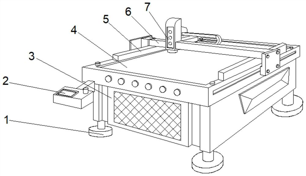
[0033] see Figure 1-2 , the present invention provides a technical solution: a machining and cutting device, including a fuselage 3, a support seat 1 is fixedly connected to both sides of the bottom of the fuselage 3, and an operation table 2 is fixedly connected to the left side of the front top of the fuselage 3 , the top of the fuselage 3 is provided with a workbench 4, and the top of the fuselage 3 is fixedly connected with clampers 5 on both sides of the workbench 4, and the top of the outer walls of both sides of the fuselage 3 is provided with a mobile frame 6, and the mobile frame 6 The top is positioned at the upper left side of the workbench 4 and is provided with a cutting device 7 .
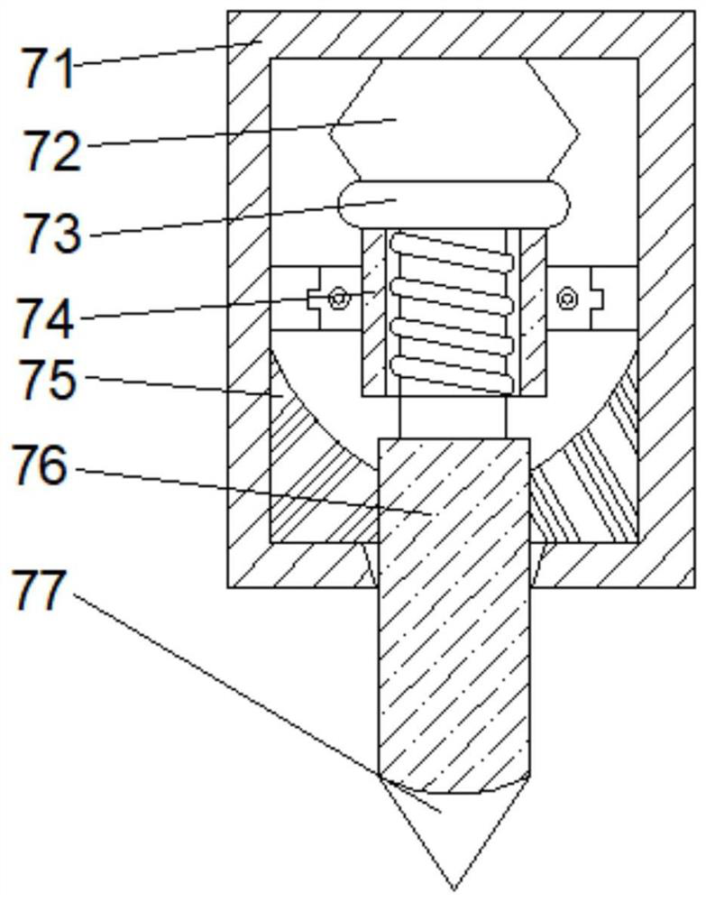
[0034]Wherein, the cutting device 7 comprises a protective cover 71, a linkage block 72 is fixedly connected between the tops of the inner cavity of the protective cover 71, a linkage rod 74 is arranged at the bottom of the linkage block 72, and a linkage rod 74 is arranged between t...
Embodiment 2
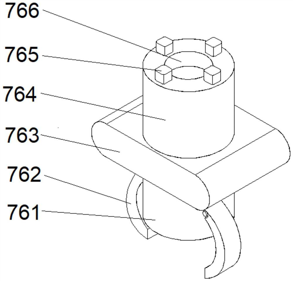
[0037] see Figure 1-4 On the basis of Embodiment 1, the present invention provides a technical solution: the auxiliary mechanism 76 includes a connecting rod 764, a fixing groove 766 is opened in the middle of the top of the connecting rod 764, and the top of the connecting rod 764 is located on both sides of the fixing groove 766. Fixedly connected with fixed block 765, the bottom of connecting rod 764 is provided with protective mechanism 763, the bottom middle position of protective mechanism 763 is fixedly connected with knife bar 761, and the both sides middle part of knife bar 761 is provided with auxiliary plate 762.
[0038] Wherein, the protective mechanism 763 includes a protective frame d1, the top of the inner cavity of the protective frame d1 is provided with a communication port d6, the inner cavity of the protective frame d1 is located on both sides of the communication port d6 and is fixedly connected with a bottom plate d2, and the bottom plate d2 is far away ...
Embodiment 3
[0041] see Figure 1-6 , on the basis of Embodiment 1 and Embodiment 2, the present invention provides a technical solution: the fixing mechanism d3 includes a fixed frame d31, and movable blocks d35 are arranged on both sides of the inner cavity top of the fixed frame d31, and the bottom of the movable block d35 is fixed A contact plate d32 is connected, a reset block d34 is fixedly connected between the movable block d35 and the contact plate d32, and guide blocks d33 are fixedly connected to both sides of the bottom of the contact plate d32.
[0042] Among them, the contact plate d32 includes a plate body t4, the top of the plate body t4 is fixedly connected with a contact surface t1, the top of the inner cavity of the contact surface t1 is provided with a positioning block t2, and the middle parts of both sides of the positioning block t2 are fixedly connected with a fixed rod t3. A support block t5 is fixedly connected between the body t4 and the contact surface t1.
[0...
PUM
 Abstract
Description
Claims
Application Information
 - R&D
- Intellectual Property
- Life Sciences
- Materials
- Tech Scout
- Unparalleled Data Quality
- Higher Quality Content
- 60% Fewer Hallucinations
Browse by: Latest US Patents, China's latest patents, Technical Efficacy Thesaurus, Application Domain, Technology Topic, Popular Technical Reports.
© 2025 PatSnap. All rights reserved.Legal|Privacy policy|Modern Slavery Act Transparency Statement|Sitemap|About US| Contact US: help@patsnap.com