Repositioning method for numerical control thread milling

A CNC milling and repositioning technology, which is applied to wire cutters, metal processing equipment, manufacturing tools, etc., can solve the problems of inaccurate tool setting, spending a lot of time, and scrapped workpieces, saving tool setting time and improving tool setting efficiency. , to avoid the effect of thread disorder

Active Publication Date: 2021-05-07
CHINA ERZHONG GRP DEYANG HEAVY IND
View PDF11 Cites 0 Cited by
  • Summary
  • Abstract
  • Description
  • Claims
  • Application Information

AI Technical Summary

Problems solved by technology

[0003] However, when the CNC milling machine is used to mill the threaded hole, when the power is cut off or the part is replaced and clamped again, there will be a problem that the tool cannot be accurately set
This is because when the threaded hole is repaired, the zero point coordinate of the milling cutter in the Z direction cannot be directly determined. The accuracy of tool setting is also poor, and it is easy to have messy threads when repairing threaded holes, which may cause scrapping of workpieces in severe cases

Method used


Image

  • Repositioning method for numerical control thread milling
  • Repositioning method for numerical control thread milling
  • Repositioning method for numerical control thread milling

Examples


Embodiment 1

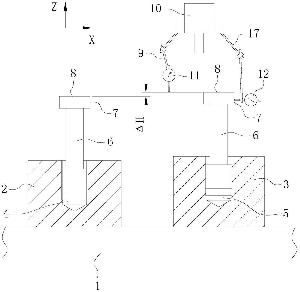
[0085] S1, see figure 1 , install the test piece 3 on the G54 coordinate system plane of the workbench 1, and determine the zero point coordinate x of the test threaded hole 5 in the X direction with the center line of the test threaded hole 5 to be processed in the test piece 3 0 ’ and the zero point coordinate y in the Y direction 0 ’; the tip of the thread milling cutter coincides with the end face of the test threaded hole 5 to be processed to determine the zero point coordinate z of the test threaded hole 5 in the Z direction 0 '.

[0086] Install the reworked part 2 on the G55 coordinate system plane of the workbench 1, and determine the zero coordinate x of the reworked threaded hole 4 in the X direction with the center line of the reworked threaded hole 4 0 and the zero point coordinate y in the Y direction 0 ;At this time, the zero point coordinate z of threaded hole 4 in the Z direction is repaired 0 Not sure yet.

[0087] S2. Mill out the test threaded hole 5 o...

Embodiment 2

[0123] S1, see Figure 5 , install the test piece 3 on the G54 coordinate system plane of the workbench 1, and determine the zero point coordinate x of the test threaded hole 5 in the X direction with the center line of the test threaded hole 5 to be processed in the test piece 3 0 ’ and the zero point coordinate y in the Y direction 0’; the tip of the thread milling cutter coincides with the end face of the test threaded hole 5 to be processed to determine the zero point coordinate z of the test threaded hole 5 in the Z direction 0 '.

[0124] Install the reworked part 2 on the G55 coordinate system plane of the workbench 1, and determine the zero coordinate x of the reworked threaded hole 4 in the X direction with the center line of the reworked threaded hole 4 0 and the zero point coordinate y in the Y direction 0 ;At this time, the zero point coordinate z of threaded hole 4 in the Z direction is repaired 0 Not sure yet.

[0125] S2. Mill out the test threaded hole 5 o...


PUM


Abstract

The invention relates to the technical field of numerical control milling, and provides a repositioning method for numerical control thread milling. The method comprises the following steps of S1, arranging a repair piece and a test piece on a workbench of a numerical control milling machine; S2, milling a test threaded hole in the test piece; and S3, under the condition that a positioning part of a thread detection positioning tool screwed into a test threaded hole and a positioning part of a thread detection positioning tool screwed into a repair threaded hole are in the same direction in the circumferential direction of the corresponding threaded hole, measuring the height difference delta H, in the Z direction, between a measuring part of the thread detection positioning tool screwed into the test threaded hole and the measuring part of the thread detection positioning tool screwed into the repair threaded hole. According to the method, through the cooperation of the test piece and the thread detection positioning tool, the zero point coordinate of the repair threaded hole in the Z direction can be indirectly determined, so that the tool setting precision when the repair threaded hole is repaired through the numerical control milling machine is ensured, and the situation that threads are disordered when the repair threaded hole is repaired through the numerical control milling machine is avoided.

Description

technical field [0001] The invention relates to the technical field of numerical control milling, in particular to a repositioning method for numerical control milling threads. Background technique [0002] The universal joint shaft of the rough rolling main drive is the key component of the hot rolling mill equipment. Because of the advanced SWZ and SWP structure, the connection type is to use high-precision threads and high-strength bolts to connect the bearing gland, bearing seat and flange fork. connected. The rotation diameter of the universal joint shaft is between Φ500-Φ1430, and the thread design specifications on the flange fork are M36X3-6H~M90X4-6H. The working conditions are very harsh, so high demands are placed on the thread accuracy on the flange yoke. At present, the threaded holes on the flange yoke are processed by CNC milling machine, which has the advantages of high processing efficiency and stable and reliable quality. [0003] However, when the CNC m...

Claims


Application Information

Patent Timeline
Patent Type & Authority Applications(China)
IPC IPC(8): B23G1/32B23G1/44
CPCB23G1/32B23G1/44
Inventor 黄涛贾富云
Owner CHINA ERZHONG GRP DEYANG HEAVY IND
Why Eureka
Try Eureka