Wheel automatic derailment type vibration supporting table

A support platform and vibration platform technology, which is applied in the field of wheel automatic derailment vibration support platform, can solve the problems of roller and steel structure damage, large space occupation, and blockage of concrete, etc., to achieve improved life, small occupation area and small resistance Effect

Pending Publication Date: 2021-05-07
咸阳怡康石油钻采配件厂
View PDF0 Cites 0 Cited by
  • Summary
  • Abstract
  • Description
  • Claims
  • Application Information

AI Technical Summary

Problems solved by technology

The current popular method is that the concrete segment mold of the shield tunnel is located on the mold trolley. After the mold trolley reaches the vibration position, it vibrates the abdomen of the mold. On the steel structure, there is a vibration damping pad under the steel structure to play the role of vibration reduction, but this design takes up a lot of space, the adjacent cavity of the roller is easy to block the concrete, and the roller and the steel structure are damaged by strong vibration, etc., so , in view of the above problems, it is necessary to improve

Method used


Image

  • Wheel automatic derailment type vibration supporting table
  • Wheel automatic derailment type vibration supporting table
  • Wheel automatic derailment type vibration supporting table

Examples


Embodiment Construction

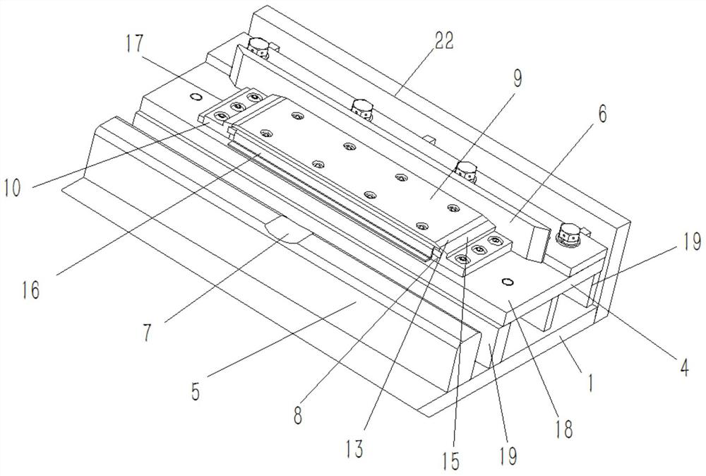
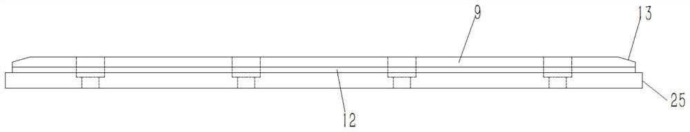
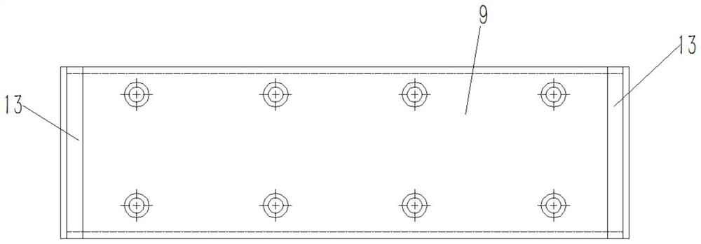
[0031] Attached below Figure 1-11 An embodiment of the present invention is described so as to clearly and completely describe the technical solution. Obviously, the described embodiment is only a part of the embodiments of the present invention, rather than all the embodiments.

[0032] In describing the present invention, it should be understood that the terms "upper", "lower", "front", "rear", "left", "right", "top", "bottom", "inner", " The orientation or positional relationship indicated by "outside", etc. is based on the orientation or positional relationship shown in the drawings, which is only for the convenience of describing the present invention and simplifying the description, rather than indicating or implying that the referred device or element must have a specific orientation, so as to Specific orientation configurations and operations, therefore, are not to be construed as limitations of the invention.

[0033] Wheel automatic derailment vibration support tab...


PUM


Abstract

Provided is a wheel automatic derailment type vibration supporting table. Supports are fixed to a vibration platform, the number of the supports is equal to that of rollers of a mold trolley, and the supports are located on the outer sides of the rollers. Guide rails are fixed to the positions, on the inner sides of the supports, of the vibration platform, the positions of the guide rails correspond to those of the rollers, and the guide rails are matched with the rollers. Derailment grooves are formed in the guide rails, and when the mold trolley moves to a vibration position in the length direction of the guide rails, the rollers are located at the derailment grooves so that the mold trolley can automatically derail from the guide rails. Damping supporting devices are arranged on the upper planes of the supports, and guide frames which are located on the outer sides of the damping supporting devices and used for guiding movement of the mold trolley are fixed to the supports. According to the wheel automatic derailment type vibration supporting table, when the mold trolley moves to the vibration position in the length direction of the guide rails, the rollers are located at the derailment grooves to complete automatic derailment of the mold trolley from the guide rails; and meanwhile, as the damping supporting devices arranged on the supports support the mold trolley with the suspended rollers, the phenomenon that the rollers are damaged when the abdomen part of a mold is vibrated is effectively avoided, the occupied area is small, and the service life of the mold trolley is effectively prolonged.

Description

technical field [0001] The invention belongs to the technical field of concrete segment prefabrication, and in particular relates to a wheel automatic derailment vibration support platform. Background technique [0002] During the prefabrication process of the concrete segment of the shield tunnel, due to its small concrete slump and high product requirements, the concrete needs to be strongly vibrated to make the concrete compact and the air to be discharged. In addition, the concrete segment mold of the shield tunnel needs to be moved In order to achieve the purpose of automated production. The current popular method is that the concrete segment mold of the shield tunnel is located on the mold trolley. After the mold trolley reaches the vibration position, it vibrates the abdomen of the mold. On the steel structure, there is a vibration damping pad under the steel structure to play the role of vibration reduction, but this design takes up a lot of space, the adjacent cavi...

Claims


Application Information

Patent Timeline
Patent Type & Authority Applications(China)
IPC IPC(8): B28B1/08B28B1/087B28B17/00
CPCB28B1/081B28B1/0873B28B17/00
Inventor 石卫杨盼李亲化刘启明赵军元解正科赵盛东
Owner 咸阳怡康石油钻采配件厂
Why Eureka
Try Eureka