Concrete mixing box

A mixing box and concrete technology, which is applied in the direction of cement mixing device, clay preparation device, unloading device, etc., can solve the problems of adhering concrete mixing, inflexible concrete mixing rotation, reducing the adjustability of output, etc.

Inactive Publication Date: 2021-05-07
李克芽
View PDF0 Cites 0 Cited by
  • Summary
  • Abstract
  • Description
  • Claims
  • Application Information

AI Technical Summary

Problems solved by technology

1. When used in the existing concrete mixing tank, it reduces the adjustability of the discharge volume when the concrete is discharged, reduces the multi-directionality of the concrete discharge, not only reduces the adjustment characteristics of the concrete discharge, but also reduces the amount of concrete discharge. At the same time, it reduces the speed and convenience of installation and disassembly to adjust the discharge when the concrete is discharged; 2. When the existing concrete mixing tank is used, the mixing efficiency of the concrete is reduced, and the mixing of the concrete when the mixing tank is used is reduced. Flexibility and stability, it is easy to have a single mixing plate during concrete mixing, which causes the inflexibility of the concrete mixing rotation; 3. When using the existing concrete mixing box, the efficiency and quickness of concrete mixing are reduced, and it is easy to appear that the concrete is in the mixing process Adhesion to the mixing tank in the medium or the phenomenon of uneven mixing in concrete production will reduce the comprehensiveness and uniformity of concrete mixing. Therefore, we propose a concrete mixing tank

Method used


Image

  • Concrete mixing box
  • Concrete mixing box
  • Concrete mixing box

Examples


Embodiment Construction

[0027] In order to make the technical means, creative features, goals and effects achieved by the present invention easy to understand, the present invention will be further described below in conjunction with specific embodiments.

[0028] In the description of the present invention, it should be noted that the terms "upper", "lower", "inner", "outer", "front end", "rear end", "both ends", "one end", "another end" The orientation or positional relationship indicated by etc. is based on the orientation or positional relationship shown in the drawings, and is only for the convenience of describing the present invention and simplifying the description, rather than indicating or implying that the referred device or element must have a specific orientation, use a specific Azimuth configuration and operation, therefore, should not be construed as limiting the invention. In addition, the terms "first" and "second" are used for descriptive purposes only, and should not be understood ...


PUM


Abstract

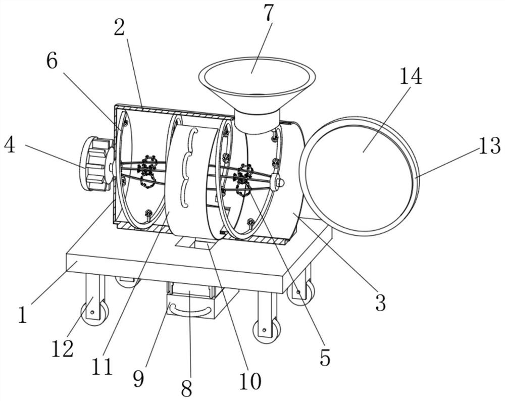
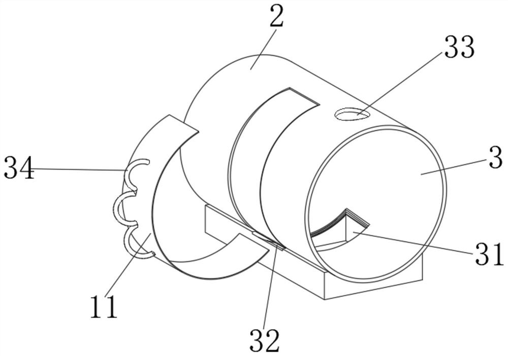
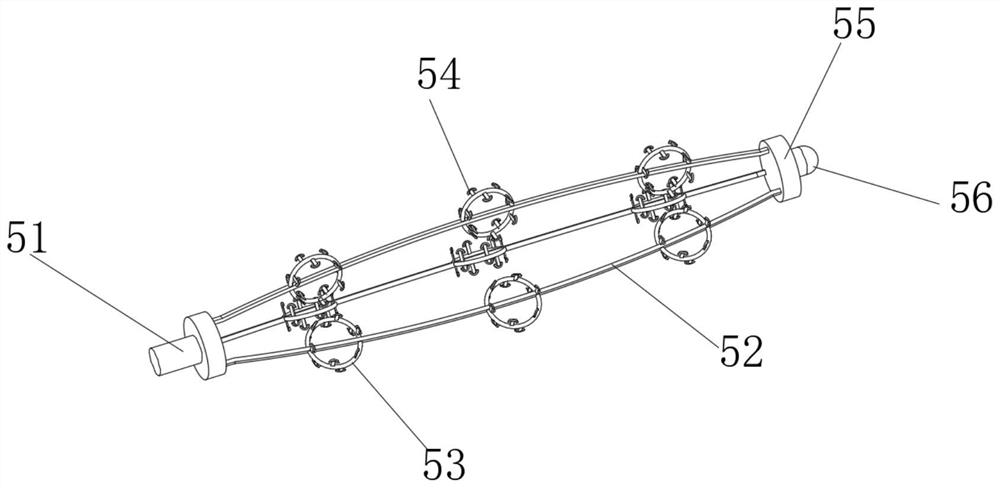
The invention discloses a concrete stirring box which comprises a stirring support, a stirring tank is fixedly connected to the middle of the upper end of the stirring support, a stirring groove is formed in the middle of the right end of the stirring tank, a motor is fixedly connected to the middle of the left end of the stirring tank, an output end of the motor penetrates through the stirring tank and is fixedly connected with a stirring structure, a connecting structure is fixedly connected to an inner groove wall of the stirring groove, a feeding hopper is fixedly connected to the middle of the right side of the upper end of the stirring tank, a discharging hopper is fixedly connected to the middle of the lower end of the stirring support, and an adjusting structure is detachably connected to the discharging hopper. According to the concrete stirring box, through the arrangement of an adjusting structure, a connecting structure and a sliding structure, the adjusting characteristic of the concrete discharging amount is improved, the multi-directionality of concrete discharging is also improved, the phenomenon that concrete stirring rotation is not flexible due to single stirring plate during concrete stirring is avoided, and the comprehensiveness and the uniformity of concrete stirring are improved.

Description

technical field [0001] The invention relates to the technical field of concrete mixing, in particular to a concrete mixing box. Background technique [0002] Concrete mixing is an operation method in which cement, lime, water and other materials are mixed and then stirred evenly. There are two types of concrete mixing: manual mixing and mechanical mixing of water. Concrete mixing plants are widely used in my country's industry, agriculture, transportation, national defense, water conservancy, municipal and other construction projects, and the demand is increasing. 1. When used in the existing concrete mixing tank, it reduces the adjustability of the discharge volume when the concrete is discharged, reduces the multi-directionality of the concrete discharge, not only reduces the adjustment characteristics of the concrete discharge, but also reduces the amount of concrete discharge. At the same time, it reduces the quickness and convenience of installation and disassembly to...

Claims


Application Information

Patent Timeline
IPC IPC(8): B28C5/14B28C5/08B28C7/16
CPCB28C5/0812B28C5/0818B28C5/0856B28C5/14B28C7/168
Inventor 李克芽
Owner 李克芽
Why Eureka
Try Eureka