
Blasting type mine single supporting pillar

A single-pillar technology, used in blasting cylinders, pillars/supports, mining equipment, etc., can solve the problems of complex hydraulic systems, difficult to move turnover, and high machining accuracy, achieve high operational flexibility, reduce manufacturing costs, and reduce machining accuracy. desired effect

Pending Publication Date: 2021-05-07
GUIZHOU JINFENG MINING
View PDF0 Cites 0 Cited by
  • Summary
  • Abstract
  • Description
  • Claims
  • Application Information

AI Technical Summary

Problems solved by technology

[0002] In the process of mineral mining, in the process of continuous excavation and extension of mine shafts, it is necessary to continue to dig deeply, and it is necessary to support the roof or surrounding rock of mine shafts. Most of the existing support devices use single hydraulic supports. The corresponding support components are supported on the roof or surrounding rock of the mine shaft. This type of single hydraulic support has the following disadvantages in practical use: one is that the hydraulic system used to drive the support to the roof or surrounding rock of the mine shaft is usually very Complicated, difficult to move and turn around, and insufficient flexibility in field use; second, in order to prevent hydraulic fluid from leaking, the machining accuracy of the corresponding parts must be high, the manufacturing cost is high, and the structure of the bracket is also complicated direction of development

Method used


Image

  • Blasting type mine single supporting pillar
  • Blasting type mine single supporting pillar

Examples


Embodiment Construction

[0019] The technical solution of the present invention is further described below, but the scope of protection is not limited to the description.

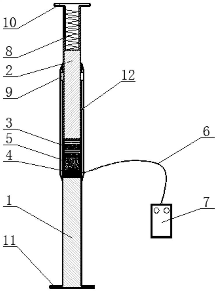
[0020] like figure 1 , figure 2 As shown, the present invention provides a blasting type mine single support pillar, including a base 1 and a push rod 2, a receiving groove is arranged on the base 1, and an elastic member 3 is fixedly connected to one end of the push rod 2 and is sleeved in the receiving groove , the other end of the push rod 2 extends outwards, and the detonator 4 and the gunpowder 5 are sequentially filled between the bottom of the receiving tank and the elastic member 3, and the detonator 4 is electrically connected to the detonator 7 arranged outside through a wire 6.

[0021] Further, it is preferred that the material of the elastic member 3 is 7075 aluminum alloy. A height adjuster 8 is also embedded in the push rod 2 . The height adjuster 8 is a cylindrical helical compression spring.

[0022] In additi...


PUM


Abstract

The invention provides a blasting type mine single supporting pillar. The blasting type mine single supporting pillar comprises a base and an ejector rod, wherein an accommodating groove is formed in the base; one end of the ejector rod is fixedly connected with an elastic piece and is arranged in the accommodating groove in a sleeving manner; a detonator and gunpowder are sequentially filled between the bottom of the accommodating groove and the elastic piece; and the detonator is electrically connected with an exploder arranged on the outside through a wire. By the technical scheme, when the exploder is started, the gunpowder is detonated through the detonator, the ejector rod and the elastic piece slide outwards, meanwhile, the elastic piece deforms and then is arranged in a limiting hole in a sleeving manner, and therefore, the purpose of supporting a mine roadway roof or surrounding rock is achieved. Compared with a common single hydraulic support in the prior art, the blasting type mine single supporting pillar has the advantages that a complicated hydraulic system does not need to be used for providing power, a supporting device is simple in structure and convenient to move and turn over, the operation flexibility is high, the problem of leakage of hydraulic fluid does not need to be considered, requirements on machining precision of corresponding parts are reduced, and the manufacturing cost is reduced favorably.

Description

technical field [0001] The invention belongs to the technical field of mining engineering equipment, and in particular relates to a blasting type mine single support pillar. Background technique [0002] In the process of mineral mining, in the process of continuous excavation and extension of mine shafts, it is necessary to continue to dig deeply, and it is necessary to support the roof or surrounding rock of mine shafts. Most of the existing support devices use single hydraulic supports. The corresponding support components are supported on the roof or surrounding rock of the mine shaft. This type of single hydraulic support has the following disadvantages in practical use: one is that the hydraulic system used to drive the support to the roof or surrounding rock of the mine shaft is usually very Complicated, difficult to move and turn around, and insufficient flexibility in field use; second, in order to prevent hydraulic fluid from leaking, the machining accuracy of the ...

Claims


Application Information

Patent Timeline
Patent Type & Authority Applications(China)
IPC IPC(8): E21D15/14E21D15/50F42B3/10
CPCE21D15/14E21D15/50F42B3/10
Inventor 吴岩佩
Owner GUIZHOU JINFENG MINING
Learn More