Real-time tracking and positioning system and method for detector in pipeline

An internal detector, real-time tracking technology, applied in the direction of special pipes, pipe components, pipes/pipe joints/fittings, etc., can solve the problems of inability to control the operation risk of the internal detector, unable to quickly make remedial measures, etc., to reduce Labor intensity and cost, improving monitoring efficiency, and avoiding safety accidents

Inactive Publication Date: 2021-05-07
SICHUAN DEYUAN PETROLEUM & GAS CO LTD
View PDF6 Cites 0 Cited by
  • Summary
  • Abstract
  • Description
  • Claims
  • Application Information

AI Technical Summary

Problems solved by technology

[0005] The purpose of the present invention is to provide a real-time tracking and positioning system and method for in-line detectors to solve the technic

Method used


Image

  • Real-time tracking and positioning system and method for detector in pipeline
  • Real-time tracking and positioning system and method for detector in pipeline
  • Real-time tracking and positioning system and method for detector in pipeline

Examples


Embodiment 1

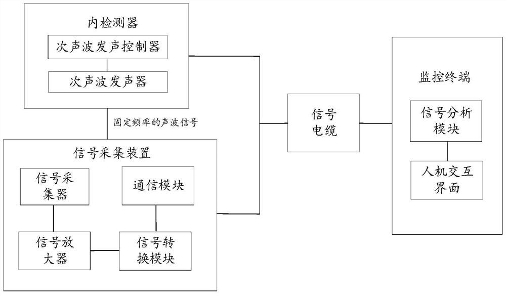
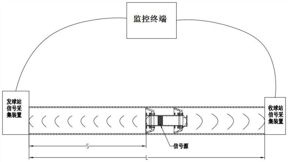
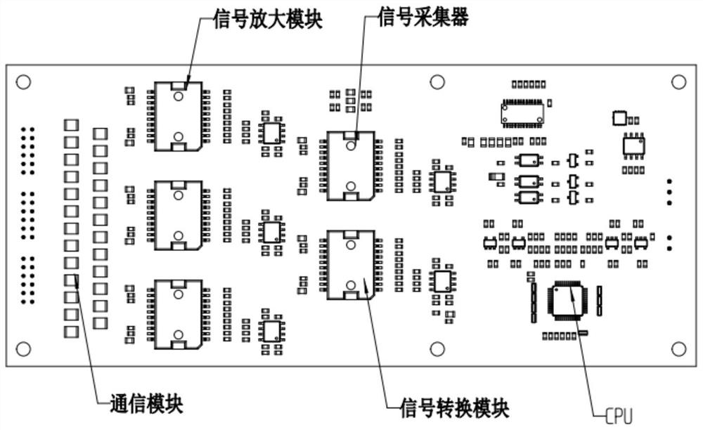
[0045] see Figure 1-3 , showing a structural schematic diagram of a real-time tracking and positioning system for an in-pipeline detector, the system comprising: an internal detector, an infrasonic generator, an infrasonic controller, a signal collection device, and a monitoring terminal; the infrasonic generator and The infrasonic sounding controllers are all arranged in the internal detector, the infrasonic sounding controller communicates with the monitoring terminal and controls the infrasonic sounding device to send out infrasonic waves; the signal acquisition device communicates with the infrasonic sounding connected to the monitoring terminal for collecting the infrasonic signal emitted by the infrasonic generator and uploading it to the monitoring terminal.

[0046] In the embodiment of the present invention, preferably, the system further includes: a signal cable, through which the signal acquisition device performs communication debugging and parameter setting with ...

Embodiment 2

[0052] see Figure 4 , the present invention also provides a real-time tracking and positioning method for in-line detectors, said method uses the above-mentioned real-time tracking and locating system for in-line detectors to perform real-time tracking and positioning for the operating status and position information of the in-line detectors; The methods described include:

[0053] Step 1: The monitoring terminal is connected to the inner detector through a signal cable, automatically recognizes the infrasonic sound controller in the inner detector, and sets the sounding frequency and time interval of the infrasonic sound generator through the infrasonic sound controller; preferably Yes, the occurrence frequency of the infrasonic wave is less than 20 Hz.

[0054] In the embodiment of the present invention, before the monitoring terminal is connected to the internal detector, a signal acquisition device is installed on the pipeline of the transceiver detection station, and th...


PUM


Abstract

The invention belongs to the technical field of pipeline detection, and discloses a real-time tracking and positioning system and method for a detector in a pipeline. The system comprises an inner detector, an infrasonic wave sounder, an infrasonic wave sounding controller, a signal collection device, and a monitoring terminal. The infrasonic wave sounder and the infrasonic wave sounding controller are both arranged in the inner detector, and the infrasonic wave sounding controller is in communication connection with the monitoring terminal and controls the infrasonic wave sounder to emit infrasonic waves. The signal collection device is in signal connection with the infrasonic wave sounder and the monitoring terminal and is used for collecting infrasonic wave signals sent by the infrasonic wave sounder and uploading the infrasonic wave signals to the monitoring terminal. According to the real-time tracking and positioning system and method for the detector in the pipeline, the real-time operation state and the specific position of the inner detector can be obtained for real-time positioning and tracking, and monitoring personnel can take measures in time according to the operation state and the specific position information of the inner detector, so that safety accidents are avoided.

Description

technical field [0001] The invention belongs to the technical field of pipeline detection, and in particular relates to a real-time tracking and positioning system and method for a detector in a pipeline. Background technique [0002] The operation of detectors in pipelines is a high-risk operation for pipeline operators. During the operation of detectors, jamming may occur, which may cause production safety accidents in pipeline enterprises. Therefore, it is very important to grasp the operating status and operating position information of the inner detector every time the detector is put into operation. [0003] In the prior art, the determination of the operating status and position of the detector in the pipeline is mainly implemented through the following scheme: by laying out calibration boxes at regular intervals along the pipeline and arranging on-site engineers to monitor, when the detector passes the calibration box , the calibration box will be excited, and the f...

Claims


Application Information

Patent Timeline
IPC IPC(8): F16L55/40
CPCF16L55/40F16L2101/30
Inventor 孙鹏王超吴昊张雄姜世强张勇
Owner SICHUAN DEYUAN PETROLEUM & GAS CO LTD
Why Eureka
Try Eureka