
A kind of spindle running equipment and its spindle running detection mechanism

A detection mechanism and spindle motor technology, applied in metal processing equipment, measuring/indicating equipment, metal processing mechanical parts, etc., can solve the problems of detection and response, encoder failure, increase production and processing costs, and achieve stable detection and response. , Simple structure design, stable and reliable operation

Active Publication Date: 2022-04-01
SHIYAN TAIXIANG INDAL
View PDF15 Cites 0 Cited by
  • Summary
  • Abstract
  • Description
  • Claims
  • Application Information

AI Technical Summary

Problems solved by technology

[0002] At present, in the field of mechanical processing, the running state of the equipment spindle determines whether it can provide continuous and stable power for continuous processing of parts. When the spindle is abnormal, such as the spindle suddenly stops due to various unforeseen reasons, or the spindle speed is not If the setting interval is not detected in time and corresponding measures are not taken, it will cause great safety accidents and quality risks, such as knife collision, equipment spindle or fixture damage, parts scrapping and other losses
[0003] At present, the commonly used CNC lathes and machining centers all use encoders to detect the spindle speed. The cost is relatively high, the structure is complex, the installation and maintenance are difficult, and the working environment is demanding.
However, for the existing non-standard equipment, due to the tight cost budget and the harsh working environment of the equipment, if the encoder continues to be used to detect the running status of the equipment spindle, it will not only increase the production and processing costs, but also the encoder will be used in harsh environments. Real-time, fast, accurate, and stable detection and response cannot be carried out under the environment. Once a failure occurs during use, it will have a serious impact on the normal operation of the entire equipment, which will cause great safety accidents and product quality risks.

Method used


Image

  • A kind of spindle running equipment and its spindle running detection mechanism
  • A kind of spindle running equipment and its spindle running detection mechanism
  • A kind of spindle running equipment and its spindle running detection mechanism

Examples


Embodiment Construction

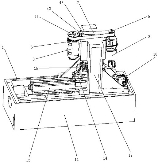
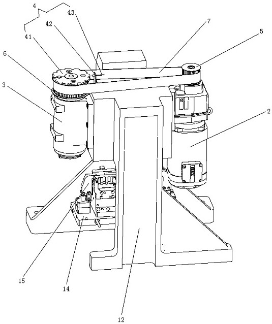
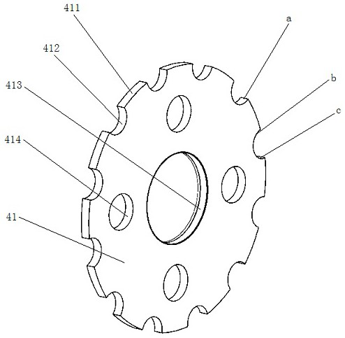
[0024] Such as Figures 1 to 3 As shown, the spindle running equipment of the present invention includes a machine tool body 1, a spindle motor 2, a power head spindle 3, a spindle running detection mechanism 4 and a machine tool electric control system.

[0025] The electric control system of the machine tool includes a PLC controller and a man-machine interface; the man-machine interface is electrically connected with the PLC controller.

[0026] The machine tool body 1 includes a workbench 11, a gantry frame 12, a guide rail 13, a slide table 14, a fixture 15 and a slide table servo motor 16; wherein, the workbench 11 is placed on the ground, and the gantry frame 12 is matched with the workbench 11 The top surface of one end of the guide rail 13 is matched with the top surface of the workbench 11; the slide table 14 is slidably installed on the guide rail 13; the slide table servo motor 16 is matched with the upper end of the workbench 11, and its power The output end is m...


PUM


Abstract

The invention relates to a spindle running device and a spindle running detection mechanism thereof. The device includes a machine tool body, a PLC controller, a spindle motor, a power head spindle and a spindle running detection mechanism; the spindle motor is electrically connected to the machine tool electric control system and the power output terminal The main pulley is installed; the power input end of the main shaft of the power head is equipped with a slave pulley; the main pulley and the slave pulley are connected by a belt; the spindle operation detection mechanism includes a code disc, a sensor fixing bracket and an inductive non-contact sensor; the code disc Installed on the power input end of the main shaft of the power head, which is located on the axial side of the slave pulley and installed coaxially with the slave pulley; the sensor fixing bracket is fixed on the upper part of the gantry frame on the side of the slave pulley; the sensor is matched and installed on the sensor fixing bracket and electrically connected with the machine tool electric control system. The structure design of the present invention is simple and reasonable, and can detect and respond to the running state of the main shaft of the power head in real time, quickly, accurately and stably.

Description

technical field [0001] The invention relates to the technical field of mechanical manufacturing, in particular to a spindle running device and a spindle running detection mechanism thereof. Background technique [0002] At present, in the field of mechanical processing, the running state of the equipment spindle determines whether it can provide continuous and stable power for continuous processing of parts. When the spindle is abnormal, such as the spindle suddenly stops due to various unforeseen reasons, or the spindle speed is not If the setting interval is not detected in time and corresponding measures are not taken, it will cause great safety accidents and quality risks, such as knife collision, equipment spindle or fixture damage, parts scrapping and other losses. [0003] At present, the commonly used CNC lathes and machining centers all use encoders to detect the spindle speed. The cost is relatively high, the structure is complex, the installation and maintenance a...

Claims


Application Information

Patent Timeline
Patent Type & Authority Patents(China)
IPC IPC(8): B23Q17/00
CPCB23Q17/00
Inventor 刘又世王永强
Owner SHIYAN TAIXIANG INDAL
Learn More