Submarine optical cable burial depth detection equipment

A technology of submarine optical cable and detection equipment, which is applied in the field of submarine optical cable buried depth detection equipment, can solve the problems of lack of effective means, difficulty in grasping construction quality by construction units, and lack of objectivity.

Pending Publication Date: 2021-05-07
武汉星辰海洋科技有限公司
View PDF0 Cites 6 Cited by
  • Summary
  • Abstract
  • Description
  • Claims
  • Application Information

AI Technical Summary

Problems solved by technology

[0004] First of all, the burial depth of the submarine optical cable is an important indicator to determine the quality of the project during the construction of the line. Due to the lack of effective means, some existing submarine optical

Method used


Image

  • Submarine optical cable burial depth detection equipment
  • Submarine optical cable burial depth detection equipment
  • Submarine optical cable burial depth detection equipment

Examples


Embodiment Construction

[0052] The present invention will be further described in detail below in conjunction with the accompanying drawings and specific embodiments to facilitate a clear understanding of the present invention, but they do not limit the present invention.

[0053] Current or moving charges generate an electric field in space and a magnetic field at the same time. If the current density in a current field in a region is only a function of spatial position, not a function of time, then such a region is called a constant current field. The corresponding electric field and magnetic field are respectively constant electric field and constant magnetic field. If a constant current is passed through both ends of a thin conductor with uniform cross-section, then the electric field distribution will be directly related to the space of the conductor and the length of both ends. At constant current, the electric field distribution is also constant.

[0054] The magnetic field generated by a co...


PUM


Abstract

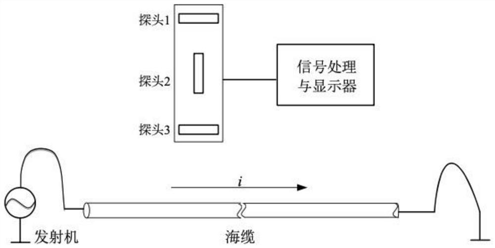
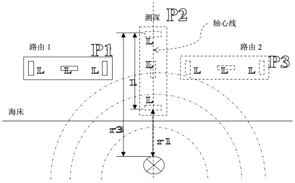
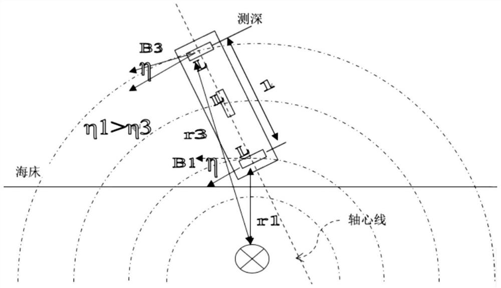
The invention provides submarine optical cable burial depth detection equipment. The submarine optical cable burial depth detection equipment comprises a transmitter, a submarine optical cable, a probe and a signal processing and displaying device. The transmitter is electrically connected with the submarine optical cable and outputs low-frequency sine waves to the submarine optical cable. The probe comprises a first coil, a second coil and a third coil, the first coil and the third coil are symmetrically arranged at the two ends of the probe, the second coil is located in the center of the probe, and the centers of the three coils are located on the same straight line. The second coil and the probe are coaxially arranged, and the axis of the first coil and the axis of the third coil are perpendicular to the axis of the probe. The probe wire moves in an area where a submarine optical cable to be detected is located. The first coil, the second coil and the third coil feed back measured induction electric signals to the signal processing and displaying device respectively. The signal processing and displaying device determines the route of the submarine optical cable and the distance between the probe and the submarine optical cable according to the three paths of induction electric signals. According to the invention, the burial depth of the submarine optical cable can be accurately determined.

Description

technical field [0001] The invention relates to the technical field of submarine optical cable communication, in particular to a submarine optical cable buried depth detection device. Background technique [0002] With the continuous development of communication technology, the widespread use of submarine optical cables around the world has become the main means of cross-sea communication. At present, there are millions of kilometers of submarine optical cables in the world. In recent years, a large number of submarine optical cable communication lines have been built along the coast of my country for the communication of garrisoned islands. Since the extensive application of submarine optical cables, due to various reasons, including human and natural factors, there are many safety problems in submarine optical cable communication lines. On the one hand, natural disasters, such as earthquakes, can directly lead to the interruption of multiple submarine optical cables, caus...

Claims


Application Information

Patent Timeline
IPC IPC(8): G01B7/26
CPCG01B7/26
Inventor 左名久
Owner 武汉星辰海洋科技有限公司
Why Eureka
Try Eureka