
A kind of OCT system sensitivity measurement method and measurement device

A technology of system sensitivity and measurement method, which is applied in the field of OCT system sensitivity measurement method and measurement device, can solve problems such as not representing noise performance, and achieve the effect of convenient measurement method, low cost and easy operation

Active Publication Date: 2022-08-05
WUHAN AGESI TECH CO LTD
View PDF5 Cites 0 Cited by
  • Summary
  • Abstract
  • Description
  • Claims
  • Application Information

AI Technical Summary

Problems solved by technology

The disadvantage of this method is that the photoelectric conversion in the OSA and beam profiler is actually different from the photoelectric receiver in the OCT system, so the obtained signal-to-noise ratio does not represent the noise performance of the entire OCT system

Method used


Image

  • A kind of OCT system sensitivity measurement method and measurement device
  • A kind of OCT system sensitivity measurement method and measurement device

Examples


Embodiment 1

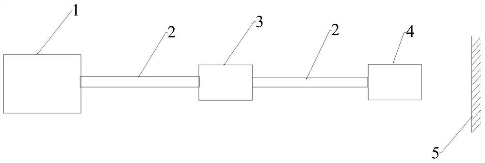
[0094] A method for measuring the sensitivity of an OCT system, comprising the following steps:

[0095] Step 1: The scanning light source sends out an optical signal;

[0096] Step 2: dividing the optical signal into an initial sampling optical signal and an initial reference optical signal;

[0097] Step 3: The initial reference optical signal enters the reference arm;

[0098] Step 4: The initial sampling optical signal enters the sampling arm, and the sampling optical signal undergoes two fixed attenuations on the sampling arm (the fixed attenuation is the first attenuation), and the attenuation of the two fixed attenuations is 2×35dB, that is, the first attenuation The attenuation is 35dB, and at the same time, it reaches the plane mirror through the fiber lens and then reflects back to the fiber lens, and the plane mirror emissivity is 80%;

[0099] Step 5: The output reference optical signal reflected from the reference arm interferes with the output sampling optical ...

Embodiment 2

[0102] Embodiments 2 and 3 differ from Embodiment 1 in that the first attenuation and the plane mirror emissivity in Embodiments 2 and 3 are different. The first attenuation of Example 2 was 37.5 dB, and the reflectivity of the plane mirror was 90%. The first attenuation of Example 3 was 40 dB, and the reflectivity of the plane mirror was 100%.


PUM


Abstract

The present application discloses a method for measuring the sensitivity of an OCT system, comprising the following steps: a scanning light source emits an optical signal; the optical signal is divided into an initial sampling optical signal and an initial reference optical signal; the initial reference optical signal enters the reference arm; the initial sampling optical signal enters the sampling arm, the sampling optical signal decays 2N+1 times in the sampling arm; the output reference optical signal reflected from the reference arm interferes with the output sampling optical signal reflected from the sampling arm to form an interference optical signal; the interference optical signal is converted into Electrical signal; convert the electrical signal into FFT spectrum, obtain the signal-to-noise ratio through the FFT spectrum, and then calculate the sensitivity of the OCT system; OCT system sensitivity = attenuation of the sampled optical signal + signal-to-noise ratio, the sensitivity of the OCT system is S, the sampled optical signal The attenuation of the optical signal is FA, and the signal-to-noise ratio is SNR, that is, S=FA+SNR; attenuation of the sampled optical signal=2N×first attenuation+second attenuation; N≥1. The present application also provides an OCT system sensitivity measurement device.

Description

technical field [0001] The present application relates to the technical field of optical interference tomography, and in particular, to a method for measuring the sensitivity of an OCT system and a measuring device. Background technique [0002] Optical interference tomography (OCT) is an ultrasound-like biomedical imaging technique. It obtains cross-sectional images and three-dimensional images of biological tissues by measuring the backscattered light or reflected light of the sample. It has the advantages of non-invasiveness, high resolution, and in vivo imaging. It has been widely used in ophthalmology, dermatology and cardiovascular Internal medicine and other clinical diagnosis and research. [0003] Early OCT systems were mainly based on time domain OCT. In order to improve the imaging speed of the OCT system, the researchers proposed the frequency domain OCT system. Compared with time-domain OCT, frequency-domain OCT has higher sensitivity. Sensitivity reflects t...

Claims


Application Information

Patent Timeline
Patent Type & Authority Patents(China)
IPC IPC(8): G01M11/02
CPCG01M11/02G01M11/0207
Inventor 王正义明良裕侯利平冯庆宇吴振英
Owner WUHAN AGESI TECH CO LTD
Learn More