Quantum absolute gravimeter and its optical path structure

An absolute gravimeter and optical path technology, applied in the measurement of gravitational fields, instruments, measuring devices, etc., can solve the problems of difficult processing, high cost, complex production, etc., to achieve compact and simplified structure, conducive to productization, and reduce the number of optical fibers Effect

Active Publication Date: 2022-06-24
杭州微伽量子科技有限公司
View PDF10 Cites 0 Cited by
  • Summary
  • Abstract
  • Description
  • Claims
  • Application Information

AI Technical Summary

Problems solved by technology

Although the system can guarantee the measurement accuracy, the entire system is too large. The structure of two-dimensional magneto-optical trap + three-dimensional magneto-optical trap leads to complex auxiliary cooling optical paths, and many laser collimation systems are introduced.
The three-dimensional magneto-optical trap component is a tetradecahedron formed by cutting off eight vertices from a cube, and holes are opened on each face of the tetradecahedron, which is complicated to manufacture and difficult to process
But the structure is still complicated, and the entire cooling optical path still needs 5 laser collimation systems
And the three-dimensional magneto-optical trap is an octagonal column, which is also difficult to process.
[0008] In addition, the design of the quantum absolute gravimeter probe by most research institutes at home and abroad is still in the stage of laboratory measurement, because the optical path structure uses more lines such as optical fibers, and uses a large number of collimation devices (such as collimation heads, etc. ), the entire vacuum system and supporting optical path are complex in structure, bulky, and expensive, and are not suitable for mobile measurement; at the same time, more optical fibers and collimation devices are also not conducive to the development of the gravimeter in the direction of miniaturization

Method used


Image

  • Quantum absolute gravimeter and its optical path structure
  • Quantum absolute gravimeter and its optical path structure
  • Quantum absolute gravimeter and its optical path structure

Examples


Embodiment approach

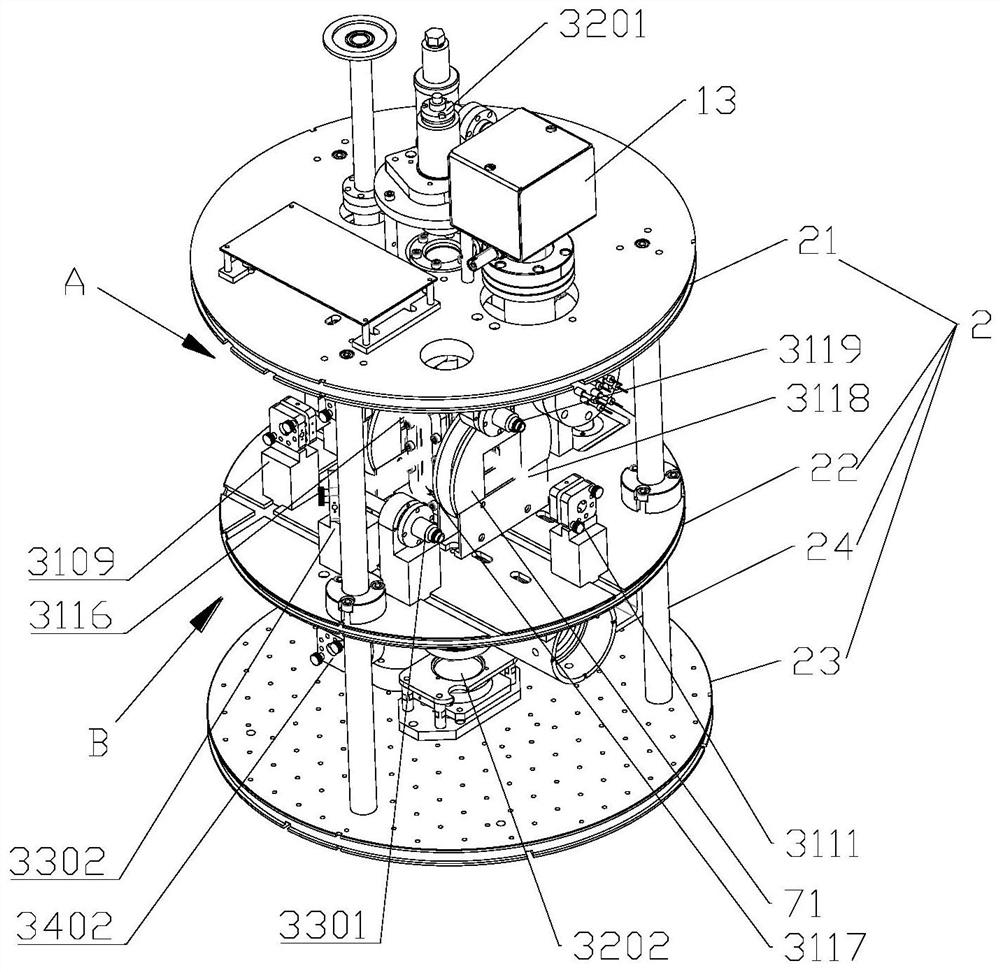
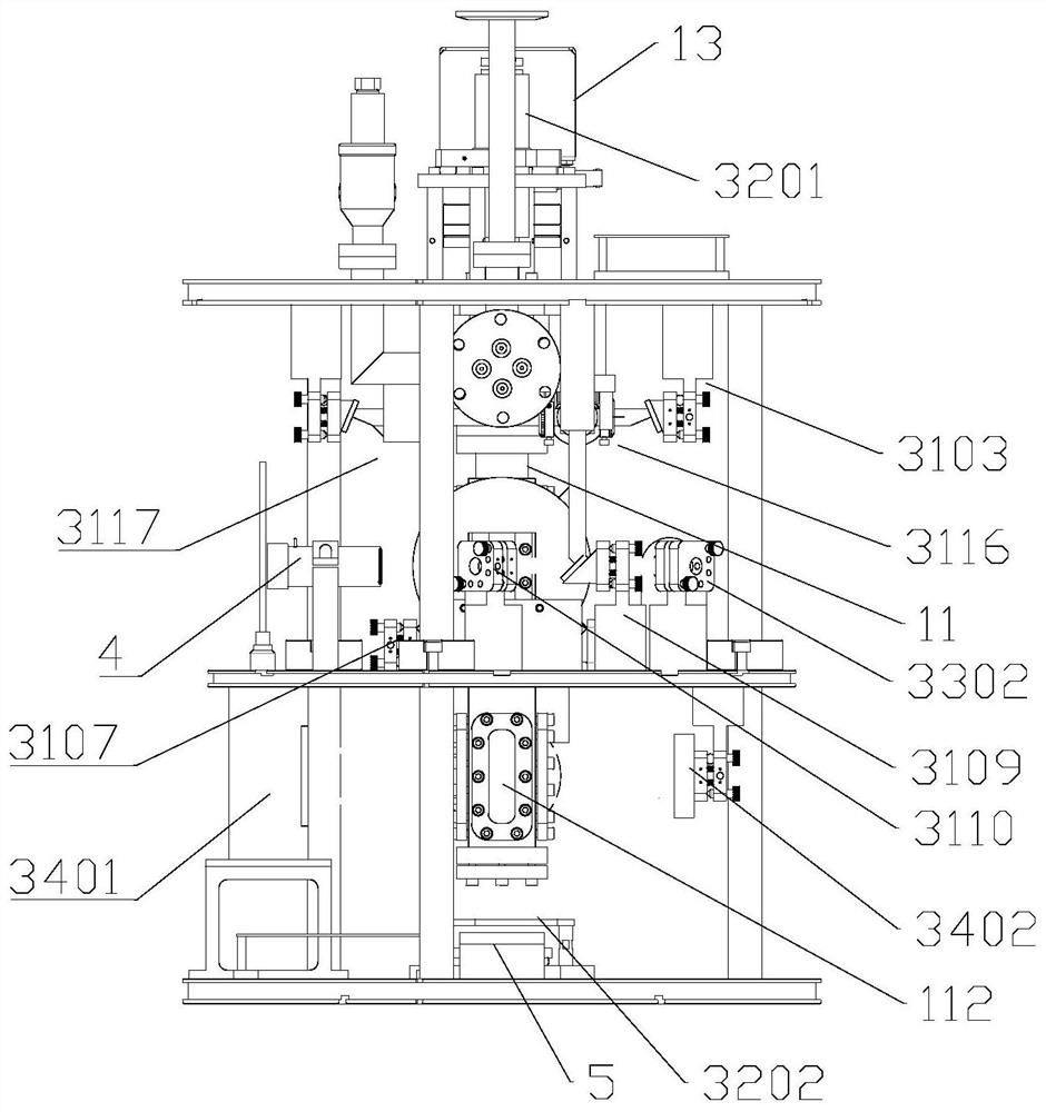
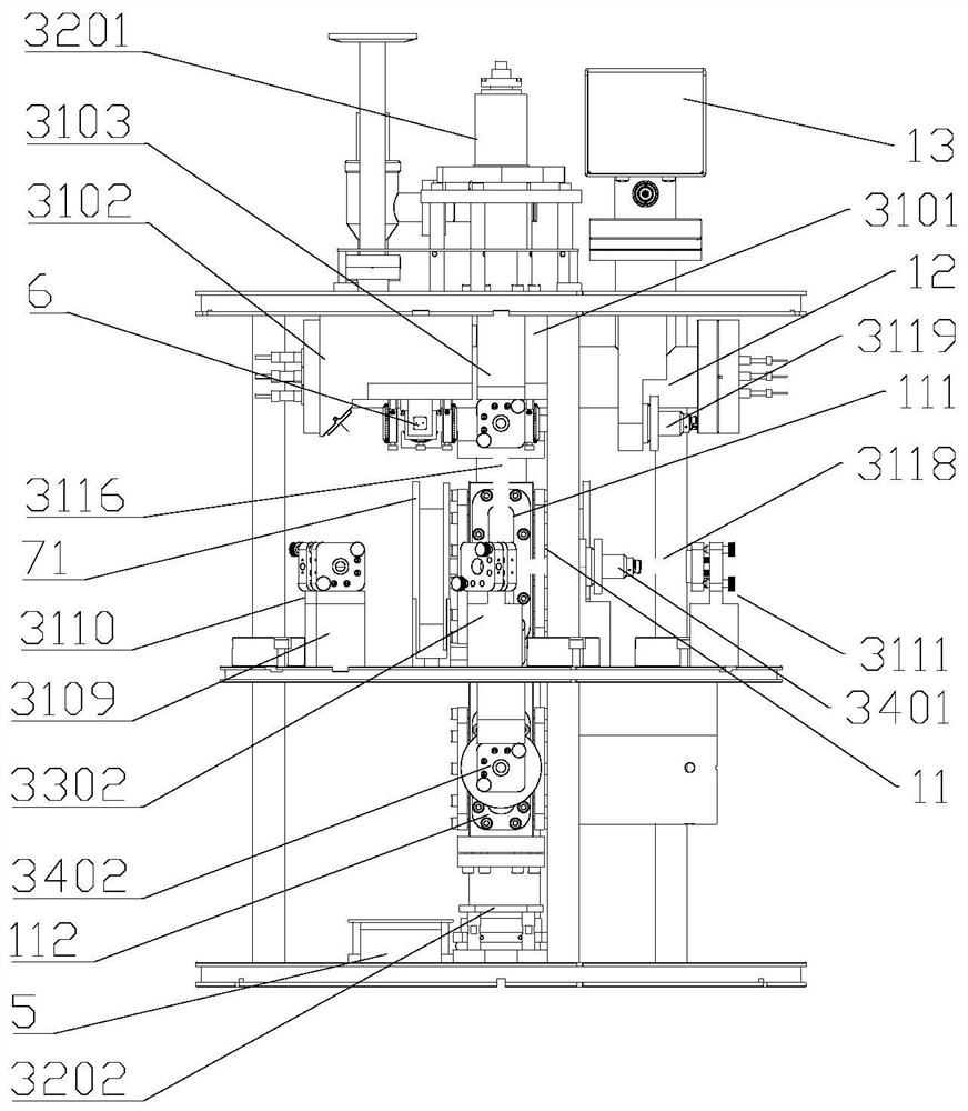
[0080] As a preferred embodiment, the first optical window 111 and the second optical window 112 both include windows 1112 , and the windows 1112 are hermetically fixed on the sidewall of the titanium alloy cavity 11 .

[0081] As a preferred implementation, such as Image 6 As shown, the side wall of the titanium alloy cavity 11 defines a stepped hole 116, the inner side of the stepped hole 116 is a long hole type, and the outer side forms a stepped groove 117 that expands toward the edge and is adapted to the shape of the window sheet 1112. The sheet 1112 is embedded in the stepped groove 117 .

[0082] As a preferred implementation, see Image 6 , the sealing assembly structure between the window 1112 and the stepped hole 116 includes an indium wire 1111, a gasket 1113 and a cover plate 1114 from the inside to the outside, wherein the indium wire 1111, the gasket 1113 and the cover plate 1114 are all In a ring shape, the indium wire 1111 is attached to the surface of the ...


PUM


Abstract

The invention discloses a quantum absolute gravimeter and its optical path structure. The optical path structure includes a first optical path structure of three laser beams used to realize a three-dimensional magneto-optical trap, a second optical path structure of three laser beams used to realize induced atomic interference. The optical path structure, the third optical path structure of the laser beam used to remove atoms in irrelevant energy levels, and the fourth optical path structure of the laser beam used to realize atom detection, the first optical path structure includes a first collimation device and The laser beam emitted by the first collimation device is divided into two beams of the first cooling beam that is inclined at 45° with respect to the vertical direction and a second cooling beam that is injected in the horizontal direction and converges with the two first cooling beams. The light splitting assembly is dispersedly arranged on the periphery of the ultra-high vacuum unit, and the maximum diameter of the light splitting assembly is smaller than the minimum diameter of the upper support plate and / or the middle support plate.

Description

technical field [0001] The invention relates to an absolute gravity measuring device, in particular to a quantum absolute gravimeter and an optical path structure thereof. Background technique [0002] High-precision gravity measuring instruments can be used in oil and gas census, mineral resource exploration, geological survey, environmental monitoring, geophysics and other fields, and the application prospect is very broad. According to different measurement methods, gravity measurement can be divided into absolute gravity measurement and relative gravity measurement. Absolute gravity measurement is to determine the absolute gravity value of a specific position in the earth's gravity field, and relative gravity measurement is to determine the gravity difference between two specific points in the earth's gravity field. Absolute gravity measurement generally adopts the dynamic method. Two methods are mainly used: one is to observe the motion of free fall, which is the meth...

Claims


Application Information

Patent Timeline
Patent Type & Authority Patents(China)
IPC IPC(8): G01V7/14
CPCG01V7/14
Inventor 杨秋海郭彬朱欣欣潘龙胜吴彬程冰
Owner 杭州微伽量子科技有限公司
Why Eureka
Try Eureka