Light transmission system and method
A technology of optical transmission and power transmission, applied in transmission systems, electromagnetic wave transmission systems, optical fiber transmission, etc., can solve problems such as poor insulation, limited transmission distance, and errors in light sources
- Summary
- Abstract
- Description
- Claims
- Application Information
AI Technical Summary
Problems solved by technology
Method used
Image

Examples
no. 1 example
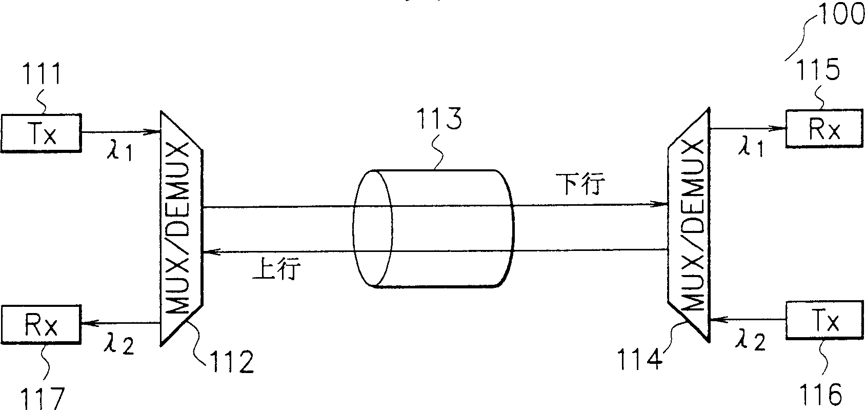
[0046] figure 1 is a schematic diagram showing the structural configuration of the bidirectional optical transmission system according to the first embodiment of the present invention. refer to figure 1 , the bidirectional optical transmission system 100 includes a downlink optical signal transmitter (Tx) 111, a first uplink / downlink signal separation multiplexer-demultiplexer (hereinafter referred to as the first MUX / DEMUX) 112, an optical fiber transmission line 113, the first Two uplink / downlink signal separation multiplexer-demultiplexer (hereinafter referred to as second MUX / DEMUX) 114, downlink optical signal receiver (Rx) 115, uplink optical signal transmitter 116, and uplink optical signal receiver 117. The downlink optical signal receiver 115 and the uplink optical signal receiver 117 respectively receive the downlink and uplink signals sent from the downlink optical signal transmitter 111 and the uplink optical signal transmitter 116 through the first MUX / DEMUX 112...
no. 2 example
[0056] Figure 4 A structural configuration diagram of bidirectional optical transmission according to the second embodiment of the present invention is schematically shown. exist Figure 4 in, with figure 1 Like parts are denoted by like numbers and need no further explanation. refer to Figure 4 , the bidirectional optical transmission system 200 includes a downlink optical signal transmitter 111, a first uplink / downlink signal splitting optical circulator (hereinafter referred to as the first optical circulator) 201, an optical fiber transmission line 113, a second uplink / downlink signal optical circulator ( Hereafter referred to as the second optical circulator) 202 , the downstream optical signal receiver 115 , the upstream optical signal transmitter 116 , and the upstream optical signal receiver 117 . The downlink optical signal receiver 115 and the uplink optical signal receiver 117 respectively receive the downlink signals sent from the downlink optical signal tran...
no. 3 example
[0066] Figure 6 is a diagram schematically showing the structural configuration of a bidirectional optical transmission system according to a third embodiment of the present invention. exist Figure 6 in, with figure 1 Like parts are denoted by like numbers and need no further explanation. refer to Figure 6 , the two-way optical transmission system 300 includes a downlink optical signal 111, a first uplink / downlink signal splitting optical digital multiplexer (hereinafter referred to as the first optical digital multiplexer) 301, an optical fiber transmission line 113, a second uplink / downlink signal optical digital multiplexer A multiplexer (hereinafter referred to as a second optical digital multiplexer) 302 , a downstream optical signal receiver 115 , an upstream optical signal transmitter 116 , and an upstream optical signal receiver 117 . Downlink optical signal receiver 115 and uplink optical signal receiver 117 respectively receive from downlink optical signal tra...
PUM
 Abstract
Description
Claims
Application Information