
Bus duct rapid to mount and dismount
A busway, fast technology, applied in the field of busway, can solve the problems of affecting use, inconvenient maintenance, and difficult adjustment, etc., to achieve the effect of facilitating use, convenient maintenance and replacement, and avoiding welding
- Summary
- Abstract
- Description
- Claims
- Application Information
AI Technical Summary
Problems solved by technology
Method used
Image

Examples
Embodiment Construction
[0029] In order to enable those skilled in the art to better understand the technical solutions of the present invention, the present invention will be further described in detail below in conjunction with the accompanying drawings.
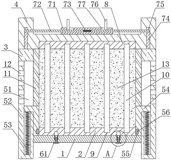
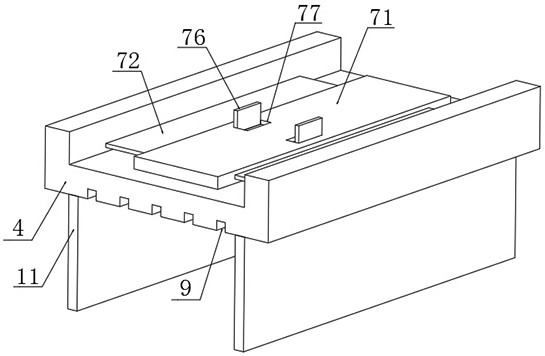
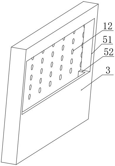
[0030] The present invention provides such as Figure 1-5 A bus duct that can be quickly installed and disassembled as shown includes a base plate 1, a first insulating plate 2 is provided on the top of the base plate 1, side plates 3 are fixed on the left and right sides of the base plate 1, and side plates 3 are fixed on the top of the side plate 3. A top plate 4 is provided, elastic mechanisms are provided inside the two side plates 3, a fixing mechanism is provided inside the bottom plate 1, and a clamping mechanism is provided on the top of the top plate 4;
[0031] The elastic mechanism is used to adjust the position of the first insulating plate 2;
[0032] The fixing mechanism is used to fix the position of the first insulating plate 2 a...
PUM
 Abstract
Description
Claims
Application Information