Network monitoring equipment with demisting mechanism

A network monitoring and equipment technology, which is applied to the camera body, the cleaning method using tools, the camera and other directions, can solve the problems of no dust cleaning, rain protection, no monitoring, etc., and achieves a simple structure, convenient use, and convenient use. Effect

Inactive Publication Date: 2021-05-07
唐春连
View PDF0 Cites 0 Cited by
  • Summary
  • Abstract
  • Description
  • Claims
  • Application Information

AI Technical Summary

Problems solved by technology

[0004] The purpose of the present invention is to solve the shortcomings of the existing network monitoring equipment with demisting mechanism, which does not have the function of protecting the monitoring from the rain during the rainy season, and does not have the function of cleaning the dust on the monitoring, and proposes a Network monitoring equipment with defogging mechanism

Method used


Image

  • Network monitoring equipment with demisting mechanism
  • Network monitoring equipment with demisting mechanism
  • Network monitoring equipment with demisting mechanism

Examples


Embodiment 1

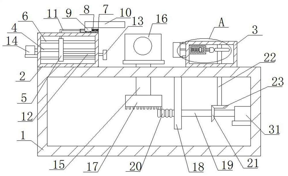
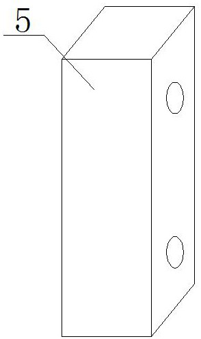
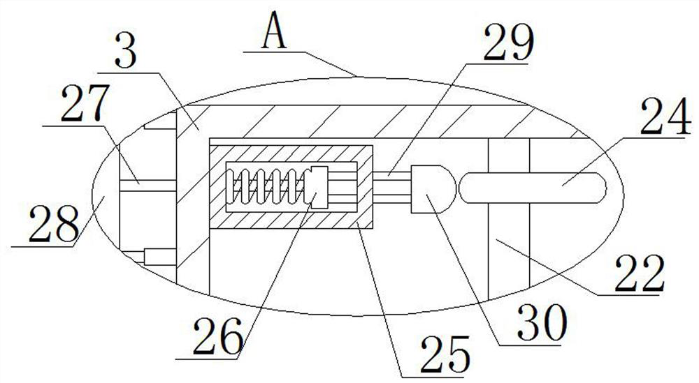
[0029] refer to Figure 1-5 , a network monitoring device with a defogging mechanism, including an installation box 1, a defogging frame 2 and a cleaning frame 3 are fixedly installed on the top of the installation box 1, and a driving screw 4 is rotatably connected to the defogging frame 2, and the driving screw 4 is There is a push long plate 5 threadedly connected, and two fixed slide bars 6 are fixedly installed in the defogging frame 2, and the two fixed slide bars 6 are both slidingly connected with the push long plate 5, and a recess 7 is fixedly installed on the top of the defogger frame 2 , one side inner wall of the recess 7 is fixedly connected with a return spring 8, one end of the return spring 8 is fixedly connected with a spring cart 9, and the top of the spring cart 9 is fixedly equipped with a rain shield 10, which pushes the long plate 5 and the spring push The same connection push rod 11 is fixedly connected between the carts 10, and a moving bar 12 is fixed...

Embodiment 2

[0040] refer to Figure 1-5 , a network monitoring device with a defogging mechanism, including an installation box 1, a defogging frame 2 and a cleaning frame 3 are welded and installed on the top of the installation box 1, and a driving screw 4 is connected to the defogging frame 2 in rotation, and the driving screw 4 is There is a push long plate 5 threadedly connected, and two fixed sliding rods 6 are welded and installed in the demisting frame 2, and the two fixed sliding rods 6 are slidingly connected with the pushing long plate 5, and the top of the defogging frame 2 is welded and installed with a recess 7 , a back-moving spring 8 is welded and connected on one side inner wall of the recess 7, and a spring trolley 9 is welded and connected to one end of the back-moving spring 8, and the top of the spring trolley 9 is welded and installed with a rain shield 10, which pushes the long plate 5 and the spring push The same connecting push rod 11 is welded and connected betwe...


PUM


Abstract

The invention belongs to the technical field of monitoring capable of cleaning dust and demisting, particularly relates to network monitoring equipment with a demisting mechanism, and aims to solve the problems that the existing network monitoring equipment with the demisting mechanism does not have a function of shielding rain for monitoring in rainy seasons and does not have a function of cleaning dust on the monitoring. The equipment comprises a mounting box, a demisting frame and a cleaning frame are fixedly mounted at the top of the mounting box, a driving screw rod is rotationally connected in the demisting frame, a long pushing plate is in threaded connection with the driving screw rod, two fixed sliding rods are fixedly mounted in the demisting frame, and the two fixed sliding rods are both in sliding connection with the long pushing plate; a concave base is fixedly installed at the top of the demisting frame, and a reset spring is fixedly connected to the inner wall of one side of the concave base. The structure is simple, dust on the monitoring head can be cleaned, the monitoring head is sheltered from rain while demisting is carried out on the monitoring head, and people can use the equipment conveniently.

Description

technical field [0001] The invention relates to the technical field of monitoring capable of cleaning dust and defogging, in particular to a network monitoring device equipped with a defogging mechanism. Background technique [0002] With the development of the times, people's technology continues to improve, and people use more and more intelligent monitoring equipment. Intelligent monitoring equipment is an embedded video server that integrates intelligent behavior recognition algorithms, which can detect pedestrians in the scene. Identify and judge the behavior of vehicles or vehicles, and generate alarms to remind users under appropriate conditions. Intelligent monitoring equipment is mostly used in public places such as parks, squares, stations, etc., and can detect abnormal behaviors of people or vehicles in time, such as running, falling, Behaviors such as chasing and beating. [0003] The existing network monitoring equipment equipped with a defogging mechanism does...

Claims


Application Information

Patent Timeline
Patent Type & Authority Applications(China)
IPC IPC(8): H04N5/225G03B17/55G03B17/56B08B1/00
CPCG03B17/55G03B17/56H04N23/52B08B1/143
Inventor 唐春连
Owner 唐春连
Why Eureka
Try Eureka