Sewage treatment device

A technology for sewage treatment devices and treatment pools, which is applied in the direction of filtration and separation, separation methods, chemical instruments and methods, etc., and can solve problems such as inability to clean the filter screen in time, inability to achieve solid-liquid separation, and single structure

Active Publication Date: 2021-05-11
湖北水云涧环保工程有限公司
View PDF9 Cites 3 Cited by
  • Summary
  • Abstract
  • Description
  • Claims
  • Application Information

AI Technical Summary

Problems solved by technology

[0004] This device cannot achieve the purpose of cleaning the filter screen in time, and cannot avoid excessive impurities to block the filter screen, which affects the normal operation of subsequent filtration work. When filtering sewage, it cannot achieve multiple deep filtration. The structure is single and solid-liquid separation cannot be achieved. For the purpose, the quality of the filtered liquid is not high, and the slow speed of the filter affects the efficiency of the filter

Method used


Image

  • Sewage treatment device
  • Sewage treatment device
  • Sewage treatment device

Examples


Embodiment 1

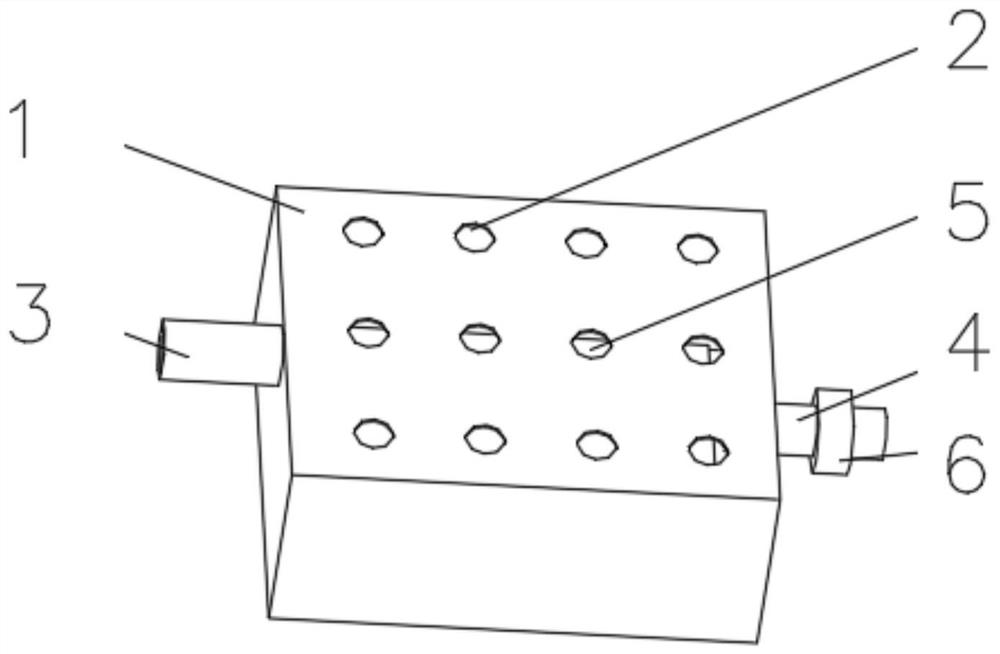
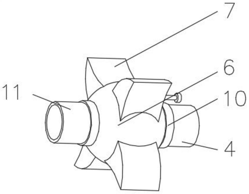
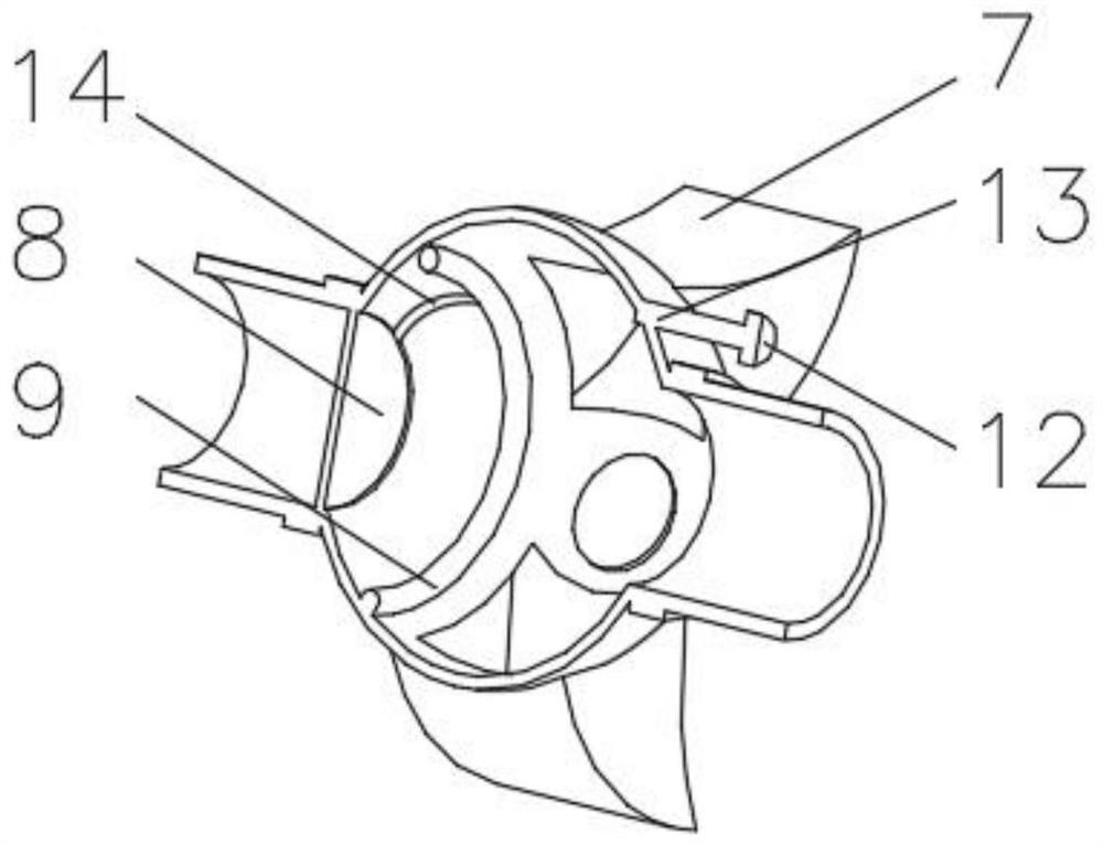
[0032] see Figure 1-4 , the present invention provides a technical solution: a sewage treatment device, comprising a treatment pool 1, one side of the treatment pool 1 is connected with a feed pipe 3, and the side of the treatment pool 1 away from the feed pipe 3 is connected with a discharge pipe 4 , the inner bottom of the treatment tank 1 is fixedly connected with a sedimentation frame 5, the outer side of the discharge pipe 4 is equipped with a filter frame 6, the outside of the discharge pipe 4 is provided with a bearing 10 near the position of the filter frame 6, and the filter frame 6 is far away from the discharge One side of the pipe 4 is communicated with a discharge pipe 11 , and a filter device 8 is installed on the inner wall of the filter frame 6 .

[0033] A motor 12 is installed outside the filter frame 6 , the output shaft of the motor 12 is rotatably connected with a rotating rod 13 , and the rotating rod 13 is fixedly connected with the filter frame 6 .

...

Embodiment 2

[0038] see Figure 1-5 , the present invention provides a technical solution: on the basis of Embodiment 1, a cleaning device 9 is installed on the inner wall of the filter frame 6 close to the filter device 8, the cleaning device 9 includes a rotating shaft 91, and the outer part of the rotating shaft 91 is sleeved with A curved plate 92, a spring 93 is installed on one side of the curved plate 92 close to the filter frame 6, and the end of the spring 93 away from the curved plate 92 is fixedly connected with a push plate 94, and the side of the curved plate 92 away from the spring 93 is installed A ball 95 is provided, and a curved groove 96 is provided on the surface of the ball 95 .

[0039]The inwall of filter frame 6 is equipped with guide rope 14 near the position of clearing device 9, and one end of guide rope 14 is fixedly connected with round frame 81, and the end of guide rope 14 away from round frame 81 is fixedly connected with arc plate 92.

[0040] When in use,...

Embodiment 3

[0043] see Figure 1-6 , the present invention provides a technical solution: on the basis of Embodiment 2, a separation device 7 is installed inside the filter frame 6, the separation device 7 includes a shell 71, and the inner wall of the shell 71 is uniformly provided with a circular groove 72, and the circular groove The inner wall of 72 is equipped with elastic plate 73, elastic plate 73 is fixedly connected with connecting plate 74 on one side away from circular groove 72, is fixedly connected with elastic net 75 between connecting plate 74, and one side of elastic net 75 is equipped with connecting rope 76 , one end of the connecting rope 76 runs through the elastic net 75, and one side of the shell 71 is provided with a material intake 77.

[0044] During use, when the rotating rod 13 drives the filter frame 6 to rotate, the centrifugal force causes the sundries in the sewage to fall into the inside of the separation device 7. At this time, the elastic plate 73 drives ...


PUM


Abstract

The invention discloses a sewage treatment device which comprises a treatment pond. One side of the treatment pond is communicated with a feeding pipe, the side, away from the feeding pipe, of the treatment pond is communicated with a discharging pipe, the bottom of the inner side of the treatment pond is fixedly connected with a precipitation frame, and the outer side of the discharging pipe is provided with a filtering frame. The position, close to the filtering frame, of the outer portion of the discharging pipe is sleeved with a bearing, the side, away from the discharging pipe, of the filtering frame communicates with a discharging pipe, a separation device is installed in the filtering frame, a filtering device is installed on the inner wall of the filtering frame, and a clearing device is installed on the position, close to the filtering device, of the inner wall of the filtering frame. A motor is mounted outside the filtering frame. The invention relates to the technical field of sewage treatment. According to the sewage treatment device, the purpose of deeply filtering sewage is achieved, the contact area of the filter screen can be changed along with the size of water flow, and the sewage treatment efficiency is improved.

Description

technical field [0001] The invention relates to the technical field of sewage treatment, in particular to a sewage treatment device. Background technique [0002] At present, in the field of sewage filtration, especially in the preliminary filtration system for removing sewage particulate impurities, filter screens are generally used for primary filtration; however, in some sewage pipes with unstable water quality, the mesh size of the filter screen is difficult to grasp. If the mesh is too fine, the filtration speed will be slow; if the mesh is too large, there may be no filtering effect at all; and in order to ensure the filtering effect, a finer mesh is generally used to adapt to the filtration of finer particles. ; In this way, the efficiency of this kind of system is very low when filtering coarser impurity particles. [0003] For example, the Chinese patent CN105561660B proposes a sewage filtration system, including a filter pipe, and the inside of the filter pipe is ...

Claims


Application Information

Patent Timeline
Patent Type & Authority Applications(China)
IPC IPC(8): B01D36/04B01D35/16
CPCB01D36/04B01D35/16B01D36/045
Inventor 冯佼
Owner 湖北水云涧环保工程有限公司
Why Eureka
Try Eureka