Shaping formwork for box girder reinforcement cage
A steel skeleton and formwork technology, which is applied in applications, household appliances, and other household appliances, etc., can solve the problems of joint wear, large box girder volume, and reduced service life of shaped formwork
- Summary
- Abstract
- Description
- Claims
- Application Information
AI Technical Summary
Problems solved by technology
Method used
Image

Examples
Embodiment 1
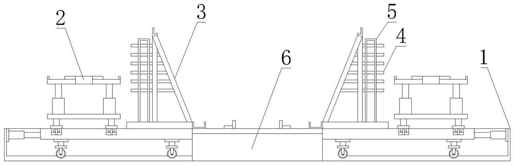
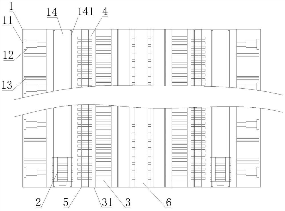
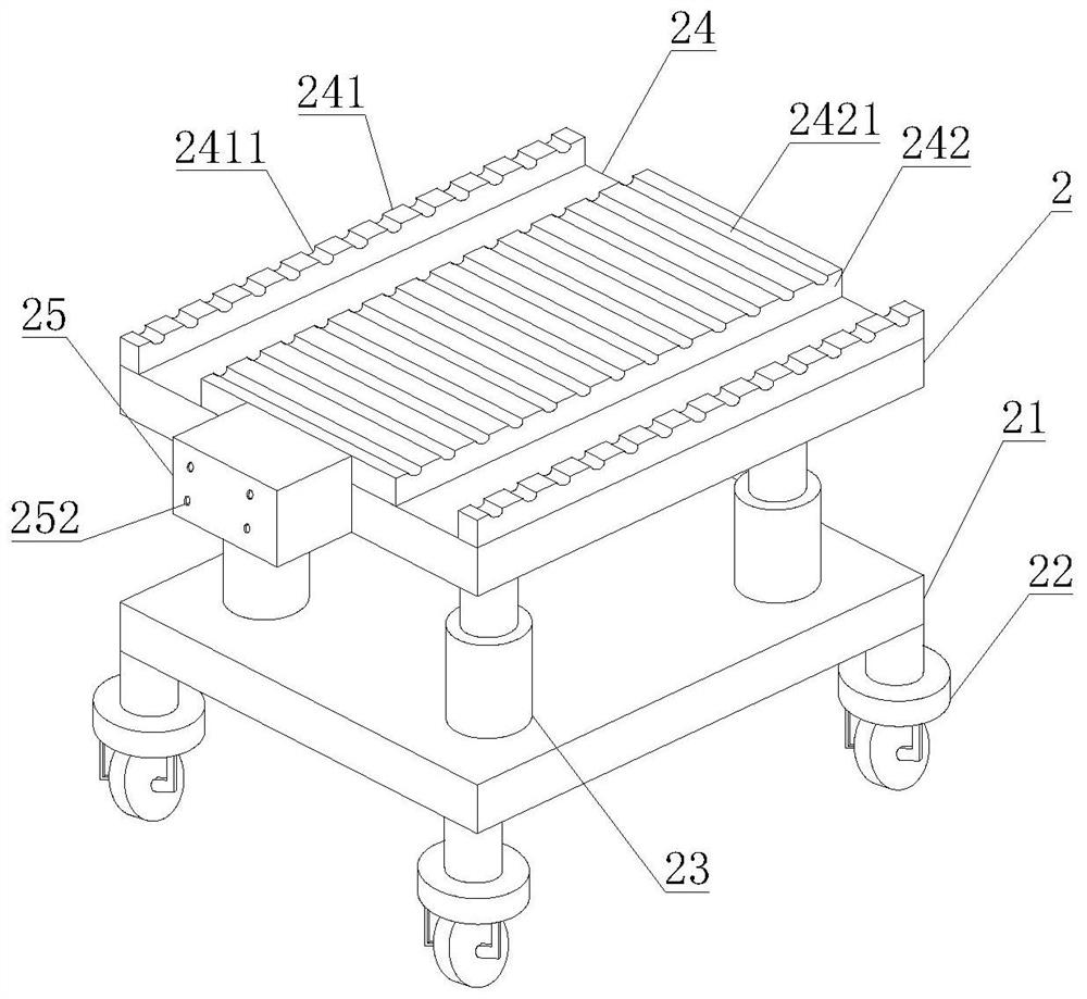
[0029] like Figure 1-7 As shown in the figure, the present invention provides a shaping formwork for a box girder steel frame, including a formwork base 1, a reinforcing bar positioning frame 3 and a base 6, the formwork base 1 includes a base body 11, and the side surface of the base body 11 is connected to the base 6. The side of the base 6 is fixedly connected, the interior of the pedestal body 11 is movably installed with a moving plate 14, the upper surface of the moving plate 14 is fixedly connected with the bottom surface of the reinforcing bar locating frame 3, and the upper surface of the moving plate 14 is fixedly installed on the reinforcing bar locating frame 3. The conveying pipe fixing rod 5 on the left side, the steel conveying pipe 4 is fixedly installed on the conveying pipe fixing rod 5, and one end of the steel conveying pipe 4 extends to the inside of the reinforcement positioning frame 3 and is fixedly connected with the steel reinforcement positioning fra...
Embodiment 2
[0034] like Figure 1-7 As shown, on the basis of Embodiment 1, the present invention provides a technical solution: preferably, the side surface of the moving plate 14 is movably connected with the side surface of the base 6, and the bottom surface of the moving plate 14 is fixedly installed with traveling wheels, and the traveling wheels are evenly distributed On the bottom surface of the moving plate 14, the bottom surface of the inner cavity of the pedestal body 11 is provided with a moving groove 13, and the moving groove 13 is slidably connected with the traveling wheel. The expansion and contraction of the hydraulic system 12 cooperates with the traveling wheels on the bottom surface of the moving plate 14 to slide in the moving groove 13, so that the moving plate 14 uses the expansion and contraction of the hydraulic system 12 to move toward the base body 11, so that the steel bars are separated from the steel bar conveying pipes 4, and the removal is completed. It avo...
Embodiment 3
[0036] like Figure 1-7 As shown, on the basis of Embodiment 1, the present invention provides a technical solution: preferably, a top beam 31 is fixedly installed on the top of the rebar positioning frame 3, and a bottom beam 61 is fixedly installed on both ends of the upper surface of the base 6, and the base The upper surface of 6 is fixedly installed with a bottom reinforcement pad 62, the bottom reinforcement pad 62 is symmetrically arranged with respect to the center line of the base 6, and a bottom reinforcement groove 621 is opened on the upper surface of the bottom reinforcement pad 62, and the bottom reinforcement slot 621 is evenly distributed on the bottom surface. On the upper surface of the reinforcing steel backing plate 62, the inner surface of the reinforcing steel conveying pipe 4 is provided with a roller groove 41, the number of the roller grooves 41 is several, and the several roller grooves 41 are evenly distributed on the inner wall of the reinforcing ste...
PUM
 Abstract
Description
Claims
Application Information
 - R&D
- Intellectual Property
- Life Sciences
- Materials
- Tech Scout
- Unparalleled Data Quality
- Higher Quality Content
- 60% Fewer Hallucinations
Browse by: Latest US Patents, China's latest patents, Technical Efficacy Thesaurus, Application Domain, Technology Topic, Popular Technical Reports.
© 2025 PatSnap. All rights reserved.Legal|Privacy policy|Modern Slavery Act Transparency Statement|Sitemap|About US| Contact US: help@patsnap.com