Automatic fan injection mold feeding and discharging gripper based on robot

A technology of automatic loading and unloading and injection molding, which is applied to household appliances, other household appliances, household components, etc., can solve the problems of low production efficiency and high risk, and achieve the effects of improving production efficiency, realizing automation and reducing operational risks

Pending Publication Date: 2021-05-11
无锡超通智能制造技术研究院有限公司
View PDF0 Cites 0 Cited by
  • Summary
  • Abstract
  • Description
  • Claims
  • Application Information

AI Technical Summary

Problems solved by technology

In particular, the loading and unloading of the fan blade mold, in addition to the blanking of the fan blades, also needs to quickly complete the pre-embedding of the mandrel and the motor casing. Because of the high precision requirements for loading and unloading, it is mainly done manually at present, and the production efficiency is low and dangerous. high sex

Method used


Image

  • Automatic fan injection mold feeding and discharging gripper based on robot
  • Automatic fan injection mold feeding and discharging gripper based on robot
  • Automatic fan injection mold feeding and discharging gripper based on robot

Examples


Embodiment 1

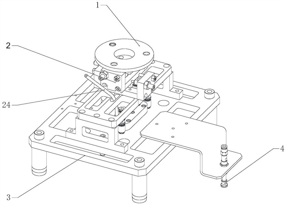
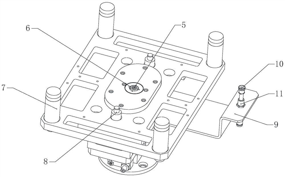
[0041] See Figure 3 to Figure 18 , the present invention consists of a robot mounting flange 1, an XY floating adjustment mechanism 2, a machine base 3, a feeding device 4, a mandrel feeding device 5, a motor shell feeding device 6, a guide shaft 7, and a precision guide shaft 8; The XY floating adjustment mechanism 2 is installed on the upper surface of the machine base 3, and the robot mounting flange 1 is installed on the XY floating adjustment mechanism 2; the motor shell feeding device 6 is installed in the middle of the lower end surface of the machine base 3, and the motor shell is loaded The front and rear sides of the device 6 are symmetrically fixedly connected with a precision guide shaft 8; the unloading device 4 is set at the position corresponding to the mandrel feeding device 5 through the support plate 9 fixedly connected to the machine base 3; the four corners of the machine base 3 are all fixed Connected with guide shaft 7; wherein, there are two sets of unl...

Embodiment 2

[0046] See figure 1 with figure 2 , the present embodiment is basically the same as Embodiment 1, and its distinguishing parts are: the unloading device 4, the mandrel loading device 5 and the motor casing feeding device 6 all have only one set, and the unloading device 4 is composed of a suction cup 10 and a buffer 11 Composition: the suction cup 10 is installed on the buffer 11; the buffer 11 is fixedly connected to the middle position of the support plate 9, and the buffer 11 is set corresponding to the position of the mandrel feeding device 5 .

[0047] The working principle of the present invention is: the machine base 1 is fixedly connected with the guide shaft 7 and the precision guide shaft 8, the guide shaft 7 realizes rough positioning, the precision guide shaft 8 realizes fine positioning, and realizes precise feeding of the mandrel and the motor shell; the mandrel The other end of the feeding hose 24 is connected to the vibrating plate, the mandrel passes through...


PUM


Abstract

The invention relates to an automatic fan injection mold feeding and discharging gripper based on a robot. The automatic fan injection mold feeding and discharging gripper is composed of a robot mounting flange plate, an XY floating adjusting mechanism, a machine base, a discharging device, a core shaft feeding device, a motor shell feeding device, a guide shaft and a precise guide shaft. The XY floating adjusting mechanism is installed on the upper surface of the machine base, and a robot mounting flange plate is mounted on the XY floating adjusting mechanism. The motor shell feeding device is mounted in the middle of the lower end face of the machine base, and precision guide shafts are symmetrically and fixedly connected to the front side and the rear side of the motor shell feeding device. The core shaft feeding device is embedded in the motor shell feeding device, and the core shaft feeding device and the motor shell feeding device are concentrically arranged. The discharging device is arranged corresponding to the position of the core shaft feeding device through a supporting plate fixedly connected to the machine base. Guide shafts are fixedly connected to four corners of the machine base. According to the gripper, discharging of fan blades, feeding of a core shaft and feeding of a motor shell can be achieved, feeding of the core shaft and feeding of the motor shell are completed synchronously, and the production efficiency is improved.

Description

technical field [0001] The invention relates to the field of injection molding machine processing, in particular to a robot-based gripper for automatic loading and unloading of fan injection molds. Background technique [0002] Industrial robots have strong versatility and can be widely used in various industrial fields, especially in some high-risk fields. Industrial robots can replace humans to ensure the safety of workers. Among them, in the field of injection molding machine production and processing, industrial robots are being widely used to replace manual loading and unloading; usually, the application of industrial robots is inseparable from robot grippers to complete the loading and unloading of workpieces. Especially the loading and unloading of the fan blade mold, in addition to the blanking of the fan blades, it is also necessary to quickly complete the pre-embedding of the mandrel and the motor casing. Because of the high accuracy of loading and unloading, it is...

Claims


Application Information

Patent Timeline
IPC IPC(8): B29C45/14B29C45/42B29C45/17B29L31/08
CPCB29C45/14008B29C45/17B29C45/42B29L2031/082
Inventor 赵飞李解乔恩理吕治玮余振华
Owner 无锡超通智能制造技术研究院有限公司
Why Eureka
Try Eureka