
Ring spinning machine and method for operating spinning position of a spinning machine

A ring spinning machine and ring spinning technology, which is applied to spinning machines, continuous winding spinning machines, textiles and papermaking, etc. It can solve problems such as the inability of the yarn guide to move up and down and difficulty in doffing. Achieve fewer thread defects, high yarn evenness, and high-quality results

Pending Publication Date: 2021-05-11
SAURER SPINNING SOLUTIONS GMBH & CO KG
View PDF16 Cites 0 Cited by
  • Summary
  • Abstract
  • Description
  • Claims
  • Application Information

AI Technical Summary

Problems solved by technology

For this reason, as also in the reciprocating yarn guide, the yarn guide cannot usually be moved up and down
In particular, the magnet assembly on the spindle also makes doffing difficult

Method used


Image

  • Ring spinning machine and method for operating spinning position of a spinning machine
  • Ring spinning machine and method for operating spinning position of a spinning machine
  • Ring spinning machine and method for operating spinning position of a spinning machine

Examples


Embodiment Construction

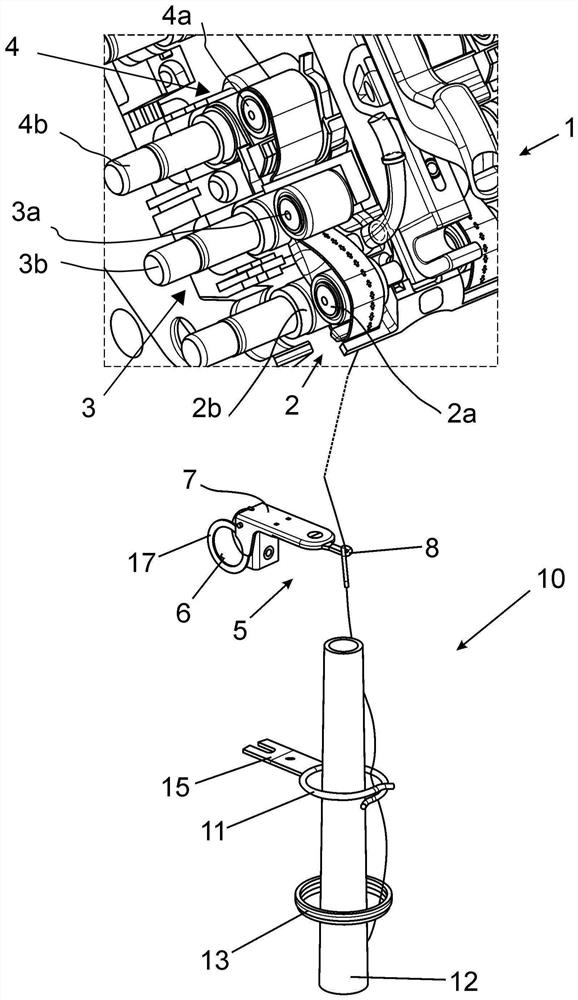
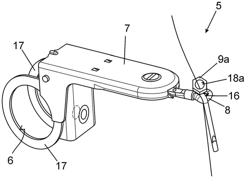
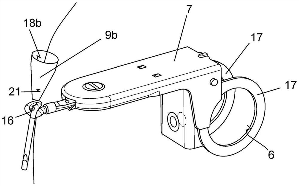
[0054] figure 1 The drafting device 1 of the spinning position of a ring spinning machine with a plurality of centrally driven Spinning bit. The main components of the spinning position are the drafting device 1 and the spindle for accommodating the tube 12 .

[0055] In the illustrated embodiment, the drafting device 1 has four pairs of rollers, namely, a pair of input rollers not shown, a pair of intermediate rollers 4, a pair of output rollers 3 and a pair of delivery rollers 2 of a compacting apparatus. . Roller pairs 2, 3, 4 are composed of upper rollers 2a, 3a, 4a and lower rollers 2b, 3b, 4b respectively. Thus, the middle roller pair 4 consists of a middle top roller 4a and a middle bottom roller 4b. The middle top roller 4a and the middle bottom roller 4b are respectively wound by draft belts. The output roller pair 3 has an output top roller 3a and an output bottom roller 3b forming a nip line on its contact line. The conveyor roller pair 2 of the agglomeration ...


PUM


Abstract

The invention relates to a ring spinning machine with a plurality of adjacent spinning stations, which has a drafting device for drafting a fiber ribbon fed to the drafting device and a ring spinning device downstream of the drafting device and with a spindle receiving a quill and winding the drafted fiber ribbon converted into a thread; and a method for operating a spinning position of a spinning machine. In order to provide a ring spinning machine and a method for operating a spinning station of a ring spinning machine, by means of which the production of a thread with a particularly high thread uniformity and low thread defects is possible, it is provided that a thread guide element is provided which has a rotationally symmetrical through opening for the thread and which is arranged in the area between the drafting device and the end of the spindle facing the drafting device rotatably around the longitudinal axis of the through opening. As a result of the rotating spindle of the ring spinning device, which is arranged downstream of the thread guide element in the thread running direction, the thread touches the inner side of the through opening and only the thread sets the thread guide element in rotation due to its rotatable arrangement.

Description

technical field [0001] The invention relates to a ring spinning machine with a plurality of spinning positions arranged adjacent to each other and to a method for operating a spinning position of a ring spinning machine, wherein the spinning position has a device for feeding a draft Its sliver drafting device, a ring spinning device downstream of the drafting device with a spindle accommodating the tube and for winding the drafted fiber sliver deformed into yarn, and a yarn guide, the The thread guide has a rotationally symmetrical opening for the yarn and is arranged rotatably about its longitudinal axis in the region between the drafting device and the end of the spindle facing the drafting device. Background technique [0002] A ring spinning machine of the type mentioned in the introduction is known, for example, from DE 199 09 501 A1. In the ring spinning machine, the fiber sliver is formed into a yarn, which is wound on a bobbin in the ring spinning machine. Ring spi...

Claims


Application Information

Patent Timeline
Patent Type & Authority Applications(China)
IPC IPC(8): D01H5/18D01H13/04D01H1/14
CPCD01H5/18D01H13/04D01H1/14B65H57/06B65H2701/31B65H57/12
Inventor E·尹斯
Owner SAURER SPINNING SOLUTIONS GMBH & CO KG
Learn More