
Cutting device for knitwear production

A cutting device and technology for knitwear, applied in the cutting of textile materials, textile and papermaking, metal processing, etc., can solve the problems of manual feeding or unloading, different cutting sizes, time-consuming and labor-intensive, etc., to achieve convenient use. Quick, easy-to-cut effects

Pending Publication Date: 2021-05-11
海宁市佰润贸易有限公司
View PDF4 Cites 1 Cited by
  • Summary
  • Abstract
  • Description
  • Claims
  • Application Information

AI Technical Summary

Problems solved by technology

[0004] The purpose of the present invention is to provide a cutting device for knitwear production, to solve the problem that the existing knitwear production cutting device proposed in the above background technology is not convenient to fix the knitwear, often because the knitwear has no It is fixed so that the cutting size may be different when cutting, which greatly increases the production cost and wastes materials, and the existing devices generally require manual loading or unloading, which is time-consuming and labor-intensive. Some devices are inconvenient to clean up the cutting desktop in time after the cutting is completed

Method used


Image

  • Cutting device for knitwear production
  • Cutting device for knitwear production
  • Cutting device for knitwear production

Examples


Embodiment Construction

[0018] The technical solutions in the embodiments of the present invention will be clearly and completely described below with reference to the accompanying drawings in the embodiments of the present invention. Obviously, the described embodiments are only a part of the embodiments of the present invention, but not all of the embodiments. Based on the embodiments of the present invention, all other embodiments obtained by those of ordinary skill in the art without creative efforts shall fall within the protection scope of the present invention.

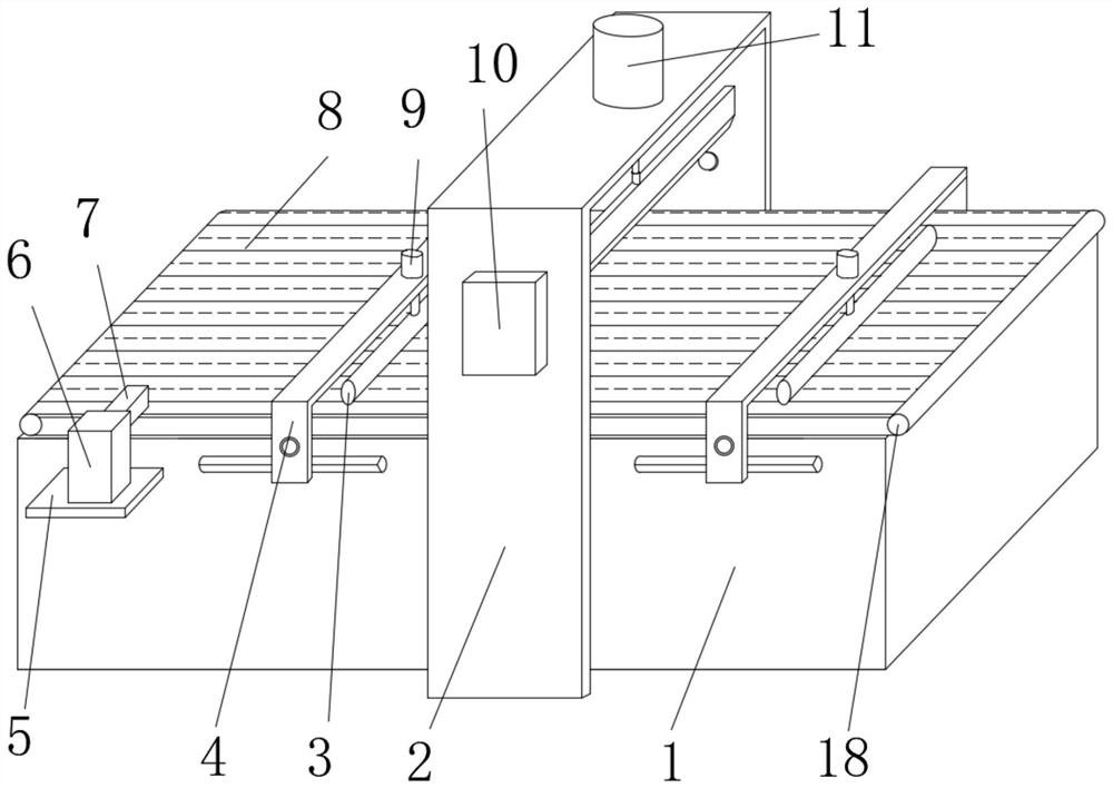
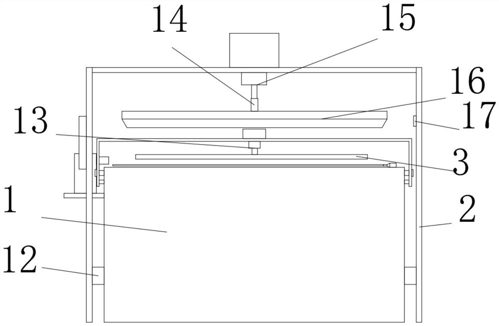
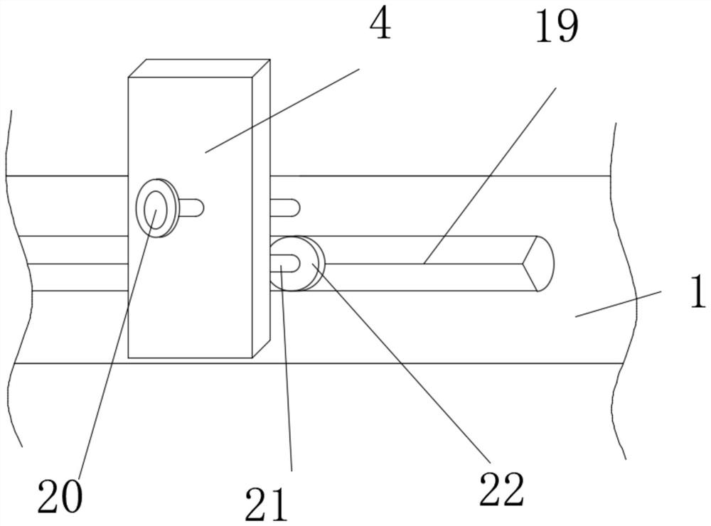
[0019] see Figure 1-4 , the present invention provides a technical solution: a cutting device for knitwear production, comprising a main body 1, a No. 1 gantry frame 2 is installed on the right side of the main body 1 near the middle position, and a No. 1 gantry frame 2 is installed at the front end near the upper side position. In the control panel 10, the front end of the main body 1 is located at the left position and is fixed wit...


PUM


Abstract

The invention discloses a cutting device for knitwear production. The cutting device comprises a main body; a first portal frame is arranged at the position, close to the middle, of the right side of the main body; a control panel is installed at the position, close to the upper side, of the front end of the first portal frame; a storage plate is fixedly connected to the position, located on the left side, of the front end of the main body; a fan is arranged at the upper end of the storage plate; an air pipe is connected to the position, close to the upper end, of the rear side of the fan; a conveying belt is arranged at the upper end of the main body; two sets of second portal frames are arranged at the position, close to the left side, of the front end of the main body; another set of second portal frames are located on the right side of the first portal frame; first air cylinders are connected to the centers of the upper ends of the two sets of second portal frames; and a second air cylinder is arranged at the position, close to the center, of the upper end of the first portal frame. When the cutting device for knitwear production is used, knitwear with different thicknesses can be cut, so that the time and labor are saved, and the cutting device is more convenient and quicker to use.

Description

technical field [0001] The invention relates to the technical field of cutting devices, in particular to a cutting device for knitwear production. Background technique [0002] Cutting device, garment processing special workbench for marking, marking, spreading and cutting. The table surface is smooth and flat, which is convenient for the cutting machine to push gently. The cutting table with a blowing and suction device forms an air cushion between the table and the bottom of the cloth layer when blowing, which can reduce the selection resistance of the cutting machine; when inhaling, a partial vacuum is formed between the top of the cloth layer and the table to compress the thickness of the cloth layer. It is convenient for cutting operation to ensure the quality of the pieces; [0003] The existing cutting device for knitwear production is inconvenient to fix the knitwear, and often because the knitwear is not fixed during use, the cutting size may be different when cut...

Claims


Application Information

Patent Timeline
IPC IPC(8): D06H7/00B26D7/18
CPCD06H7/00B26D7/1854
Inventor 林小军
Owner 海宁市佰润贸易有限公司
Learn More