
Spliced structure type lifting guide rail

A guide rail and structural technology, applied in the direction of building structure support, building structure support, building structure support scaffolding, etc., can solve problems such as poor bending resistance, poor installation accuracy, and weak splicing connection rigidity

Pending Publication Date: 2021-05-11
甘肃圣华源科技有限公司
View PDF0 Cites 1 Cited by
  • Summary
  • Abstract
  • Description
  • Claims
  • Application Information

AI Technical Summary

Problems solved by technology

[0003] The purpose of the present invention is to provide a method of splicing joints of the lifting guide track structure of an attached lifting scaffold, which aims to solve the problem of weak structure splicing connection rigidity, poor bending resistance and poor installation accuracy of the existing scaffold track, which is easy to be installed during use. The problem of breaking and destroying

Method used


Image

  • Spliced structure type lifting guide rail
  • Spliced structure type lifting guide rail
  • Spliced structure type lifting guide rail

Examples


Embodiment Construction

[0018]In order to make the objectives, technical solutions and advantages of the present invention, the present invention will be described in further detail below with reference to the accompanying drawings and examples. It should be understood that the specific embodiments described herein are merely intended to illustrate the invention and are not intended to limit the invention.

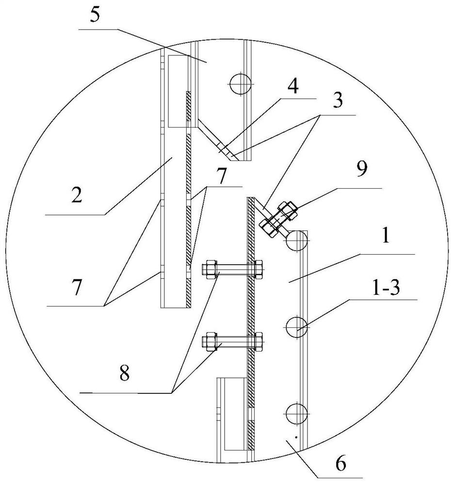
[0019]Such asFigure 1 ~ 4Disted, wherefigure 1 It is a front elevational view of the lifting guide rail structure of the attachment of the attachment of the present invention;figure 2 Yesfigure 1 A top view of the lifting guide orbital structure;image 3 It is a schematic diagram of a lifting guide orbital structure splicing joint;Figure 4 Yesfigure 2 A cross-sectional view of A-a.

[0020]The embodiment of the present invention discloses a splicing structural elevator guide rail, which is spliced ​​from a number of the splicing units, and the splicing unit comprises a guide rail 1 and a vertical rod 2, a gui...


PUM


Abstract

The invention discloses a spliced structure type lifting guide rail. The rail is formed by splicing a plurality of splicing units in a linear end-to-end sequence, wherein each splicing unit comprises a guide rail body and a vertical rod welded to the guide rail body, and end steel plates are welded to the end faces of the two ends of the guide rail body; the two ends of each splicing unit are a head end and a tail end correspondingly, wherein the end of the guide rail body in the head end protrudes out of the end of the vertical rod, and the end of the vertical rod in the tail end protrudes out of the end of the guide rail body; and in the spliced structure of every two adjacent splicing units in the relation of an upper section and a lower section, the vertical rod at the tail end of the upper section of splicing unit is fastened to the guide rail body at the head end of the lower section of splicing unit through a bolt, and the end steel plates of the two guide rail bodies of the upper section of splicing unit and the lower section of splicing unit are fastened in cooperation with bolts after being attached. According to the spliced structure type lifting guide rail, a staggered inclined connection manner is adopted, the force transmission path is greatly improved, the rail splicing contact cross section is enlarged, and the strength and rigidity of the guide rail and a vertical main frame are enhanced.

Description

Technical field[0001]The present invention belongs to a scaffolding fitting, and in particular, the present invention relates to a spliced ​​structural elevator guide rail of a attachment lifting scaffold.Background technique[0002]In most adhesive lifting scaffolding, the lifting-oriented rail structure splicing joint is weak, poor anti-bending ability, poor installation accuracy, easy to deform in use, the prior art cannot solve the above technical problems.Inventive content[0003]It is an object of the present invention to provide an attachment-oriented rail structural splicing node approach to the attachment of the fastener, which is designed to solve the structural splicing connection of the existing scaffolding track, poor anti-bending ability, poor installation accuracy, easy to use A problem of breaking damage occurs.[0004]The present invention is achieved, a splicing structural lifting guide rail, which is spliced ​​from a plurality of the splicing units, and the splicing uni...

Claims


Application Information

Patent Timeline
IPC IPC(8): E04G3/28E04G5/00
CPCE04G3/28E04G5/00E04G2003/286
Inventor 史圣华包继德陈生林武世敏
Owner 甘肃圣华源科技有限公司
Learn More