Supercharge Your Innovation With Domain-Expert AI Agents!

Divergent cooling air film hole distribution structure of supersonic turbine blade

A technology of divergent cooling and turbine blades, applied in the direction of blade support components, engine components, machines/engines, etc., can solve the problems of easy deformation and ablation of the divergent cooling layer, achieve simple and fast processing, reduce usage, and ensure The effect of intensity

Active Publication Date: 2021-05-11
HARBIN INST OF TECH
View PDF14 Cites 2 Cited by
  • Summary
  • Abstract
  • Description
  • Claims
  • Application Information

AI Technical Summary

Problems solved by technology

[0004] However, when divergent cooling is subjected to high-temperature thermal shock, the divergent cooling layer is easily deformed and ablated due to high-temperature thermal stress. It is especially important to ensure the strength and structural integrity of the divergent cooling material while ensuring cooling efficiency. Therefore, providing a The divergent cooling air film hole distribution structure of a supersonic turbine blade is very necessary to improve the strength of the material as much as possible under the premise of ensuring the cooling efficiency, and to improve the service life of the parts to be cooled

Method used


Image

  • Divergent cooling air film hole distribution structure of supersonic turbine blade
  • Divergent cooling air film hole distribution structure of supersonic turbine blade
  • Divergent cooling air film hole distribution structure of supersonic turbine blade

Examples


Embodiment 1

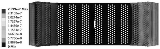
[0040] Example 1: Periodic zigzag air film hole distribution model

[0041] Such as figure 2 As shown, the distribution of air film holes on the divergent cooling layer in this embodiment includes a dense area and an array structure area. The dense area is located at one end of the divergent cooling layer, and the rest of the area on the divergent cooling layer except the dense area is an array structure area.

[0042] The array structure area is arranged in a periodic zigzag array, specifically: the air film holes are distributed in a periodic zigzag band along the longitudinal direction of the divergent cooling layer, and each zigzag band is composed of a number of air hole units arranged in an equilateral triangle. A pore unit is composed of 6 air film holes, the distance between adjacent air film holes is 0.5 mm, the connection line of the center of the 6 air film holes forms an equilateral triangle, and one side of the triangle of each air pore unit on a zigzag belt is l...

Embodiment 2

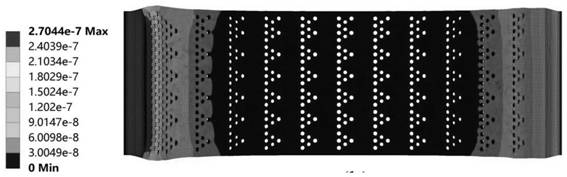
[0046] Embodiment 2: Periodic prismatic air film hole distribution model

[0047] Such as image 3 As shown, the distribution of air film holes on the divergent cooling layer in this embodiment includes a dense area and an array structure area. The dense area is located at one end of the divergent cooling layer, and the rest of the area on the divergent cooling layer except the dense area is an array structure area.

[0048] The array structure area is arranged in the form of a periodic prism array, specifically: the air film holes are distributed in a periodic prism along the longitudinal direction of the divergent cooling layer, the center distances of adjacent prisms are the same, and adjacent rows of prisms are arranged alternately; A prism is made up of 4 gas film holes, and the center line of the 4 gas film holes forms a prism, and the distance between adjacent gas film holes is 0.5 mm. The distance between phase prisms is 0.8 millimeters, and the diameter of air film h...

Embodiment 3

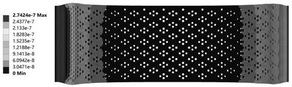
[0052] Example 3: Periodic corrugated gas film hole distribution model

[0053] Such as Figure 4 As shown, the distribution of air film holes on the divergent cooling layer in this embodiment includes a dense area and an array structure area. The dense area is located at one end of the divergent cooling layer, and the rest of the area on the divergent cooling layer except the dense area is an array structure area.

[0054] The array structure area is arranged in the form of a periodic corrugated array, specifically: the gas film holes are distributed in the form of periodic corrugated strips along the longitudinal direction of the divergent cooling layer, and the distance between adjacent corrugated strips is 2.5 mm. Each corrugated strip is composed of two mirrored Each sawtooth belt is composed of a number of air hole units arranged in an equilateral triangle. Each air hole unit is composed of six air film holes. The distance between adjacent air film holes is 0.5 mm. 300 ...


PUM

PropertyMeasurementUnit
Pore diameteraaaaaaaaaa

Abstract

The invention discloses a divergent cooling air film hole distribution structure of a supersonic turbine blade, and belongs to the technical field of active cooling modes of aircraft power systems. The problem that when existing divergent cooling is subjected to high-temperature thermal shock, a divergent cooling layer is extremely prone to deformation and ablation due to high-temperature thermal stress is solved. Distribution of divergent cooling air film holes in a divergent cooling layer comprises a dense area and an array structure area, the dense area is located at one end of the divergent cooling layer, and the array structure area is arranged in a periodic sawtooth shape, a periodic prismatic shape, a periodic corrugated shape, a periodic rectangle shape or a periodic quadrilateral shape. According to the divergent cooling air film hole distribution structure, mutual support is formed between rib plates, the stress concentration phenomenon of the rib plates is avoided, deformation of the rib plates is reduced, the original shape of micron-sized air film holes is guaranteed, blocking of the air film holes is reduced, and on the premise that the air film cooling efficiency is guaranteed, the heat flow impact effect is effectively isolated, and ablation of a hot end component is reduced.

Description

technical field [0001] The invention relates to a divergent cooling air film hole distribution structure of a supersonic turbine blade, and belongs to the technical field of active cooling methods of aircraft power systems. Background technique [0002] Divergent cooling is a high-efficiency film cooling method for high-temperature, supersonic incoming flow. With the further increase of the flight speed of hypersonic aircraft, the thermal environment faced by key parts such as the leading edge of the aircraft, engine thrust chamber, and supersonic turbine blades will become more severe. As the most efficient active thermal protection technology at present, divergent cooling can not only improve cooling efficiency and temperature uniformity by using porous media materials, but also control the cooling process in a timing, positioning, and quantitative manner, which helps to realize large-area, reusable Thermal protection, promoting the intelligent regulation of the thermal p...

Claims


Application Information

Patent Timeline
IPC IPC(8): F01D5/18
CPCF01D5/186
Inventor 温风波苏良俊韩佳骏万晨昕王松涛
Owner HARBIN INST OF TECH
Features
  • R&D
  • Intellectual Property
  • Life Sciences
  • Materials
  • Tech Scout
  • Unparalleled Data Quality
  • Higher Quality Content
  • 60% Fewer Hallucinations
Learn More