Water-cooled flange with embedded circulating water path

A technology of water-cooled flanges and circulating water circuits, which is used in flange connection, pipe heating/cooling, pipe/pipe joint/pipe fittings, etc. lower problem

A technology of water-cooled flanges and circulating water circuits, which is used in flange connection, pipe heating/cooling, pipe/pipe joint/pipe fittings, etc. lower problem

CN112780856APending Publication Date: 2021-05-11RES INST OF PHYSICAL & CHEM ENG OF NUCLEAR IND

Image

  • Water-cooled flange with embedded circulating water path
  • Water-cooled flange with embedded circulating water path
  • Water-cooled flange with embedded circulating water path

Examples


Embodiment Construction

[0033] In order to better understand the purpose, structure and function of the present invention, below in conjunction with appendix Figure 1-7 , understanding of the present invention.

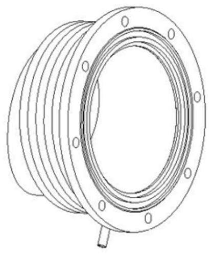
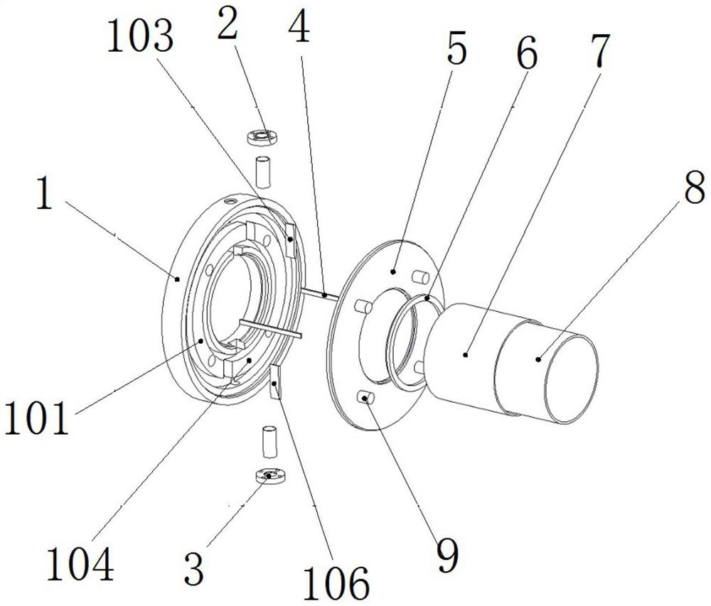
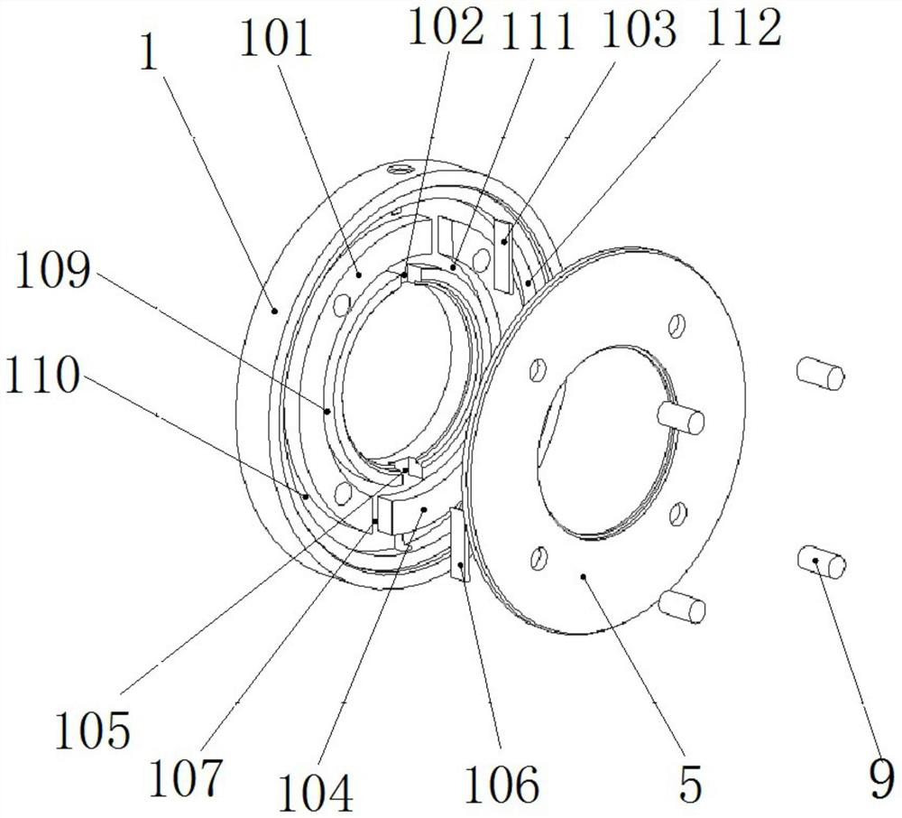
[0034] The present invention uses the form embedded in the vacuum flange to realize the function of directly contacting the heat source to cool down. The structure embedded in the vacuum flange is designed with a circulating cooling water circuit in the middle, and there is a cooling water circuit at the flange port. The water inlet and outlet can realize the circulation of cooling water, and a sealing structure is designed on the end face of the water-cooling flange, which can be used as a link between the vacuum flange and the vacuum tank, and at the same time does not affect the original function of the corresponding vacuum flange.

[0035] The water-cooled flange adopts the form of embedded cooling water circuit, which solves the problem that the local temperature of the vacuum flange i...


PUM


Abstract

The invention discloses a water-cooled flange with an embedded circulating water path. The water-cooled flange comprises a cylindrical flange with an annular water tank cavity and a cylindrical water cover with which the cylindrical flange is covered, wherein the inner ring of the cylindrical flange is connected with a flange sleeve; a cylindrical cavity formed in the flange sleeve is connected with the annular water tank cavity in a penetrating mode; the flange sleeve and the cylindrical flange are coaxially arranged; one end of the cylinder flange is connected with a water inlet in a penetrating mode; the other end of the cylinder flange is connected with a water outlet in a penetrating mode; and water flowing through the water inlet flows out through the cylindrical flange, the cylindrical water cover and the water outlet, so that water cooling is achieved.

Description

technical field [0001] The invention belongs to the technical field of flanges, in particular to a water-cooled flange with an embedded circulating water channel. Background technique [0002] In the use environment of some vacuum devices, there will be local high temperature and unsatisfactory heat dissipation conditions, which will cause device failure, malfunction and damage for a long time, and even cause economic property losses and personal injuries. Therefore, it is necessary to take effective measures against the local thermal effect of vacuum equipment. Generally, the tank body of vacuum equipment is designed with built-in or externally added cooling water channels to prevent the temperature rise and heat accumulation of the vacuum tank body under relevant heating experiments, but the number of cooling water channels that come with the vacuum tank itself is limited. , cannot take into account all parts of the vacuum tank, and heat accumulation will occur in some fl...

Claims


Application Information

Patent Timeline
11 May 2021
Publication
CN112780856A
IPC
F16L23/032; F16L53/70
CPC
F16L23/032; F16L53/70
Inventors
闫超; 赵国华