Emergency braking mechanism of electric vehicle brake-by-wire system and method thereof

An electric vehicle, emergency braking technology, applied in the direction of brake actuators, brake components, brake types, etc., can solve the problems of long braking time, low braking efficiency, brake pump damage, etc., to avoid softening, safety The effect of improved performance and improved braking efficiency

Pending Publication Date: 2021-12-24
ANHUI TECHN COLLEGE OF MECHANICAL & ELECTRICAL ENG
View PDF6 Cites 0 Cited by
  • Summary
  • Abstract
  • Description
  • Claims
  • Application Information

AI Technical Summary

Problems solved by technology

[0005] In order to make up for the deficiencies in the prior art, although the existing brake pump has a certain braking effect on the car, there is only one brake pump, the braking efficiency is relatively low, the braking time is still relatively long, and the brake pump will In the event of damage, there is still a large potential safety hazard in an emergency. The invention proposes an emergency braking mechanism and method for an electric vehicle brake-by-wire system

Method used


Image

  • Emergency braking mechanism of electric vehicle brake-by-wire system and method thereof
  • Emergency braking mechanism of electric vehicle brake-by-wire system and method thereof
  • Emergency braking mechanism of electric vehicle brake-by-wire system and method thereof

Examples


Embodiment 1

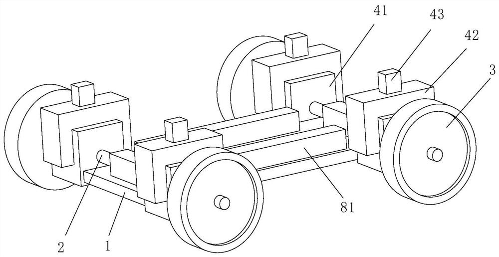
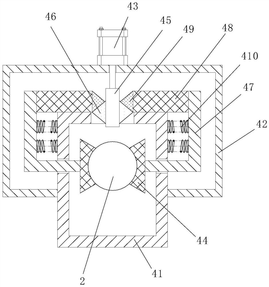
[0036] Such as Figure 1 to Figure 7As shown, the emergency braking mechanism of a brake-by-wire brake system for an electric vehicle according to the present invention includes an automobile chassis 1, a rotating shaft 2, a wheel 3 and a braking structure; the wheels 3 are connected to two ends of the rotating shaft 2; The automobile chassis 1 is connected with the vehicle frame; the brake structure includes a No. 1 housing 41, a No. 2 housing 42, an electric cylinder 43 and a brake block 44; side wall, and the top of the No. 1 casing 41 penetrates and is affixed to the No. 2 casing 42; the electric cylinder 43 is fixed to the top of the No. 2 casing 42; the output end of the electric cylinder 43 is affixed to the No. Rod 45; two triangular prisms 46 are symmetrically fixed to the outer wall of the No. One end inside the housing 41 is fixedly connected to the brake block 44, and one end of the L-shaped rod 47 located outside the first housing 41 is fixedly connected to the s...

Embodiment 2

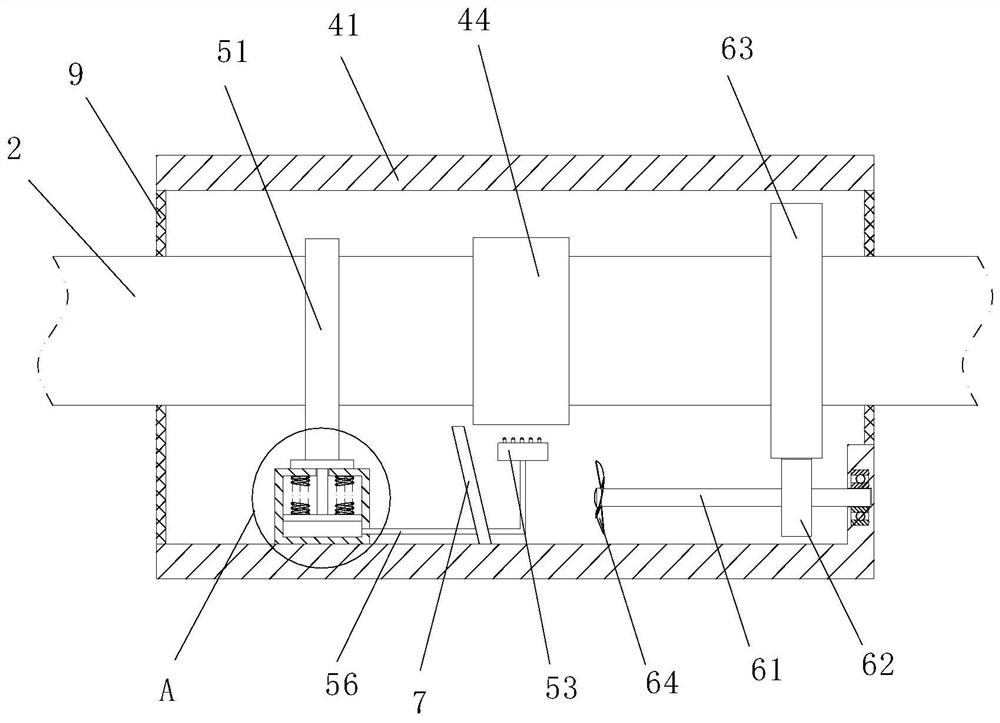
[0051] see Figure 8-Figure 9 , Comparative Example 1, as another embodiment of the present invention, the rodless cavity of the water tank 52 is provided with a cooling tube 10; during operation, the cold water inside the water tank 81 flows to the water tank 52, realizing the cooling of the water tank 52 The addition of internal cold water, in order to ensure the cooling effect of the water in the water tank 52, a refrigeration pipe 10 is provided, and the refrigeration pipe 10 will realize the cooling of the water in the water cylinder 52.

[0052] Working principle: When the electric vehicle encounters a dangerous situation, the electric vehicle will perform emergency braking, and the control system of the electric vehicle will activate the electric cylinder 43, so that the electric cylinder 43 drives the No. 1 rod 45 to move downward, so the triangular prism 46 will continue to Extrusion fitting block 49 (initially, half area of ​​triangular prism 46 bottoms are all press...


PUM


Abstract

The invention belongs to the technical field of electric vehicles, and particularly relates to an emergency braking mechanism of an electric vehicle brake-by-wire system and a method thereof. The emergency braking mechanism comprises a vehicle chassis, a rotating shaft, wheels and a braking structure; the wheels are connected to the two ends of the rotating shaft; the vehicle chassis is connected with a vehicle frame; the braking structure comprises a first shell, a second shell, an electric cylinder and braking blocks; the first shell is fixedly connected to the side wall of the vehicle chassis, and the top of the first shell penetrates through and is fixedly connected to the second shell. The electric cylinder is fixedly connected to the top of the second shell; the output end of the electric cylinder is fixedly connected with a first rod. The two braking blocks clamp the rotating shaft, so that the rotating shaft stops rotating, and emergency braking is achieved; and meanwhile, the emergency braking mechanism is used in cooperation with an electric vehicle brake pump, the braking efficiency is improved, the problem that after a single braking mechanism is damaged, the braking system completely breaks down is avoided, and the safety performance is improved.

Description

technical field [0001] The invention belongs to the technical field of electric vehicles, and in particular relates to an emergency braking mechanism and a method thereof for a wire-controlled braking system of an electric vehicle. Background technique [0002] Electric vehicles are new types of vehicles that use electricity as the driving energy, and do not produce air-polluting gases during driving. [0003] In the prior art, electric vehicles generally use a brake pump as a braking tool. When braking, the brake pads are pushed, and the brake pads rub against the brake drum, so that the speed of the vehicle is reduced and stopped. [0004] Although the existing brake pump has a certain braking effect on the car, there is only one brake pump, the braking efficiency is relatively low, the braking time is relatively long, and the brake pump will be damaged. There are still relatively large potential safety hazards; therefore, the present invention provides an emergency braki...

Claims


Application Information

Patent Timeline
Patent Type & Authority Applications(China)
IPC IPC(8): F16D49/16F16D65/18F16D65/807F16D121/24
CPCF16D49/16F16D65/186F16D65/807F16D2121/24
Inventor 王波丁芳刘明岩田苗法祖冉徐康俊朱仁闻王寿运王志强彭丽媛
Owner ANHUI TECHN COLLEGE OF MECHANICAL & ELECTRICAL ENG
Why Eureka
Try Eureka