Power device used for garbage compression

A power device and garbage compression technology, which is applied to fluid pressure actuators, fluid pressure actuation system components, servo motors, etc., can solve the problems of large reversing impact, heavy power device weight, and high oil temperature of equipment, and achieve extended Longer service life, avoiding oil pump damage, avoiding the effect of bursting

Inactive Publication Date: 2019-03-01
扬州海纳尔液压设备有限公司
View PDF0 Cites 0 Cited by
  • Summary
  • Abstract
  • Description
  • Claims
  • Application Information

AI Technical Summary

Problems solved by technology

[0002] At present, the working environment of the garbage compression system is harsh, and the working time is long. Generally, it takes 8-10 hours continuously, and the work intensity is high. The traditional garbage compression power unit has the following problems due to unreasonable design: (1) Start with load and do not have cooling capacity , causing the oil temperature of the equipment to be as high as 85°C, and the failure rate is high; (2) The continuous operation has poor stability and poor performance, resulting in the accumulation of garbage on site, which cannot be processed and transferred in time, affecting environmental sanitation and the normal work and life of residents; (3) The power unit The self-weight is relatively heavy, up to about 200kg. At least two people are required to cooperate to pull it out during maintenance and installation. The efficiency is low. At the same time, too high self-weight will directly affect the loading capacity of each garbage, increasing the fuel consumption of the car and (4) When the compression box is driven by the power device to compress the garbage, the running noise is high and the reversing impact is large, which has a very bad impact on the lives of the surrounding residents.

Method used


Image

  • Power device used for garbage compression

Examples


Embodiment Construction

[0019] In order to facilitate the understanding of the present invention, the following will be described in conjunction with the accompanying drawings and embodiments.

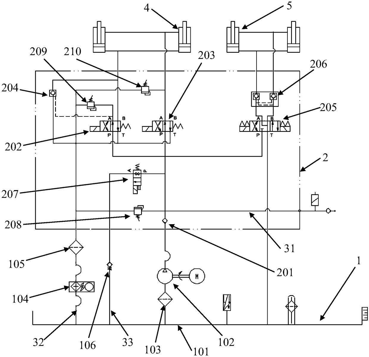
[0020] refer to figure 1 It can be seen that the present invention discloses a power device for garbage compression, including a fuel tank assembly 1, a hydraulic valve group assembly 2 and a power assembly; wherein, the fuel tank assembly 1 includes a fuel tank 101 for carrying hydraulic oil and a communication For the oil pump 102 of the oil tank 101, the hydraulic valve group assembly 2 includes a one-way valve 201, a first two-position four-way solenoid valve 202, a second two-position four-way solenoid valve 203 and a hydraulic control check valve 204, and the one-way valve 201 The inlet of the check valve 201 is connected to the oil outlet of the oil pump 102, and the outlet of the check valve 201 is respectively connected to the P oil port of the first two-position four-way solenoid valve 202 and the P...


PUM


Abstract

The invention provides a power device used for garbage compression. The power device comprises a fuel tank assembly, a hydraulic valve bank assembly and a power assembly. The fuel tank assembly comprises a fuel tank and an oil pump. The hydraulic valve bank assembly comprises a one-way valve, a first two-position four-way electromagnetic valve, a second two-position four-way electromagnetic valveand a hydraulic control one-way valve. An inlet of the one-way valve communicates with an oil outlet of the oil pump. An outlet of the one-way valve communicates with a P oil port of the first two-position four-way electromagnetic valve and a P oil port of the second two-position four-way electromagnetic valve through an oil inlet pipe. A T oil port of the first two-position four-way electromagnetic valve and a T oil port of the second two-position four-way electromagnetic valve communicate with the fuel tank through a main oil return pipe. A branch oil return pipe is arranged on the main oilreturn pipe. The main oil return pipe and the oil inlet pipe communicate with a two-position two-way electromagnetic valve. An inlet of the hydraulic control one-way valve communicates with the main oil return pipe. The power assembly comprises a push oil cylinder communicating with the first two-position four-way electromagnetic valve. By means of the power device provided by the invention, the operating noise can be lowered, the service life can be prolonged, and the continuous operating stability is guaranteed.

Description

technical field [0001] The invention relates to the field of brazing of water-cooled plates, in particular to a power device for garbage compression. Background technique [0002] At present, the working environment of the garbage compression system is harsh, and the working time is long. Generally, it takes 8-10 hours continuously, and the work intensity is high. The traditional garbage compression power unit has the following problems due to unreasonable design: (1) Start with load and do not have cooling capacity , causing the oil temperature of the equipment to be as high as 85°C, and the failure rate is high; (2) The continuous operation has poor stability and poor performance, resulting in the accumulation of garbage on site, which cannot be processed and transferred in time, affecting environmental sanitation and the normal work and life of residents; (3) The power unit The self-weight is relatively heavy, up to about 200kg. At least two people are required to coopera...

Claims


Application Information

Patent Timeline
Patent Type & Authority Applications(China)
IPC IPC(8): F15B21/08F15B11/16F15B13/06F15B21/041F15B21/0423
CPCF15B21/087F15B11/16F15B13/06F15B21/041F15B21/042
Inventor 薛磊徐路
Owner 扬州海纳尔液压设备有限公司
Why Eureka
Try Eureka