Method and device for calibrating flow coefficient of orifice plate by adopting pressure method

A technology of flow coefficient and calibration hole, which is applied in the field of gas flow testing and calibration, and can solve problems such as high pressure, potential safety hazards, and exceeding the acceptable range of the container

Pending Publication Date: 2021-05-11
RES INST OF PHYSICAL & CHEM ENG OF NUCLEAR IND
View PDF0 Cites 0 Cited by
  • Summary
  • Abstract
  • Description
  • Claims
  • Application Information

AI Technical Summary

Problems solved by technology

[0003] However, the following problems exist in the process of calibrating the flow coefficient of an orifice plate with a large or small diameter using the conventional weighing method: (1) the diameter of the orifice plate is too small, the gas flow through the orifice plate is small within a certain period of time, and the weighing The weighing deviation of the container loaded with gas during the weighing process seriously affects the accuracy of the gas weighing data; (2) The diameter of the orifice plate is too large, and the pressure in the container loaded with gas during the weighing process is too high, which exceeds the acceptable range of the container, posing a safety hazard , making the method difficult to implement

Method used


Image

  • Method and device for calibrating flow coefficient of orifice plate by adopting pressure method

Examples


Embodiment 1

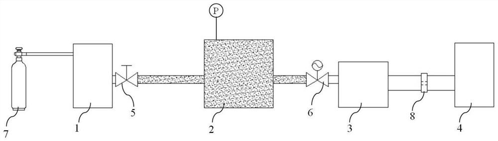
[0034] like figure 1 As shown in the figure, a device for calibrating the flow coefficient of an orifice plate by a pressure method includes a feeding container 1, a feeding pressure-relief tank 2, a pressure-stabilizing tank 3 and a receiving container 4 that are communicated in turn through a vacuum pipeline. The feeding container 1 The outlet is provided with a valve 5, an electric pressure regulating valve 6 is provided between the supply pressure relief tank 2 and the pressure stabilization tank 3, and the orifice plate 8 is arranged in the vacuum pipeline between the pressure stabilization tank 3 and the material receiving container 4. The pressure relief tank 2 is connected with a pressure measuring device.

[0035] The device for calibrating the flow coefficient of the orifice plate by the pressure method further includes a high-pressure gas cylinder 7 which is communicated with the supply container 1 or the supply pressure relief tank 2 .

Embodiment 2

[0037] Based on the device of Embodiment 1, a method for calibrating orifice flow coefficient by pressure method, comprising the following steps:

[0038] (I) Use the standard volume to measure the volume V of the reference area; the reference area is the area between the valve 5 and the electric pressure regulating valve 6, namely figure 1 middle fill area;

[0039] (II) Evacuate the system after the valve 5, start the test after the evacuation is completed, and maintain the temperature T of the system and the test environment during the test 0 constant;

[0040] (Ⅲ) Electric pressure regulating valve to stabilize P K1 , measure Δt 1 Time reference area pressure drop ΔP 1 ;

[0041] (IV) According to the design of different electric pressure regulating valve voltage regulation value P Ki , repeat step (III), measure the corresponding Δt i Time gray area pressure drop ΔP i ;

[0042] (Ⅴ) When the pressure of the supply buffer tank is not enough, use a high-pressure ga...


PUM


Abstract

The invention discloses a method and a device for calibrating a flow coefficient of an orifice plate by adopting a pressure method, and the method comprises the following steps: measuring the pressure change to obtain the relationship between multiple groups of pressure and flow, and further fitting the slope and intercept of a flow coefficient function expression. The device comprises a feeding container, a feeding slow pressure tank, a pressure stabilizing tank and a receiving container which are sequentially communicated through a vacuum pipeline, a valve is arranged at an outlet of the feeding container, an electric pressure regulating valve is arranged between the feeding slow pressure tank and the pressure stabilizing tank, and a pore plate is arranged in the vacuum pipeline between the pressure stabilizing tank and the receiving container. According to the invention, mass weighing is not needed; the number of test points is not limited by the number of collection containers in a weighing method, and the test points can be freely increased; the flow coefficients of pore plates with different pore diameters can be measured by adjusting the volume V of the gray area, and the calibration range of the pore plates is wide; the influence of weight error of the weighing and receiving container is avoided; and the potential safety hazard of excessive gas collected by the material collecting container is avoided.

Description

technical field [0001] The invention belongs to the field of test and calibration of gas flow, in particular to a method and a device for calibrating the flow coefficient of an orifice plate by a pressure method. Background technique [0002] In a vacuum system, it is usually necessary to stably pass a certain amount of gas into the vacuum pipeline. The gas flow control needs to be realized by installing an orifice plate with a certain aperture, and the gas flow rate passing through the orifice plate in a certain period of time is calculated by the orifice plate flow formula. The orifice flow formula is a linear function expression related to the pressure in front of the orifice. The flow coefficient of the orifice plate is obtained by linear fitting of the data corresponding to the flow rate of multiple pressure points, and the slope and intercept of the linear function expression are obtained, which are used to determine the gas flow value in the subsequent use of the ori...

Claims


Application Information

Patent Timeline
Patent Type & Authority Applications(China)
IPC IPC(8): G01F25/00
CPCG01F25/15
Inventor 杨坤
Owner RES INST OF PHYSICAL & CHEM ENG OF NUCLEAR IND
Why Eureka
Try Eureka