Eureka AIR delivers breakthrough ideas for toughest innovation challenges, trusted by R&D personnel around the world.

High-pressure fluid nozzle detection workbench

A technology for testing workbenches and high-pressure fluids. It is used in measuring devices, mechanical parts testing, and machine/structural parts testing. It can solve problems such as affecting production, time-consuming and labor-intensive, and incompatible nozzle models, specifications, and models.

Pending Publication Date: 2021-05-11
福州赋达机电有限公司
View PDF0 Cites 0 Cited by
  • Summary
  • Abstract
  • Description
  • Claims
  • Application Information

AI Technical Summary

Problems solved by technology

[0003] The above detection method is not only time-consuming and labor-intensive, but the key point is that there are only subtle differences in the shape of many nozzles of different specifications and models. It is difficult to distinguish nozzles of different specifications and models. During production and assembly, it is easy to have no quality problems with the nozzle itself but the assembled nozzle model Abnormal problems such as incompatibility with the required specifications and models. There is currently no effective detection method to control this situation. It is often confused during production and assembly, and often needs to be reworked and replaced, which affects production.

Method used


Image

  • High-pressure fluid nozzle detection workbench
  • High-pressure fluid nozzle detection workbench
  • High-pressure fluid nozzle detection workbench

Examples


Embodiment Construction

[0025] Below in conjunction with accompanying drawing and specific embodiment the present invention is described in further detail:

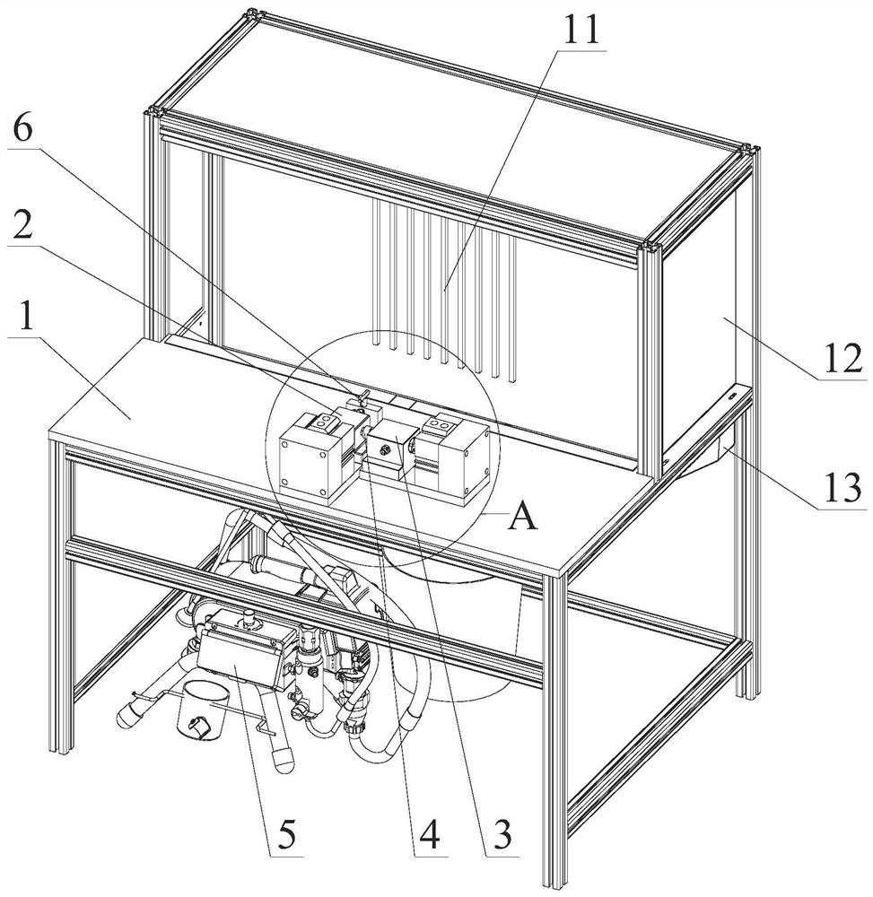
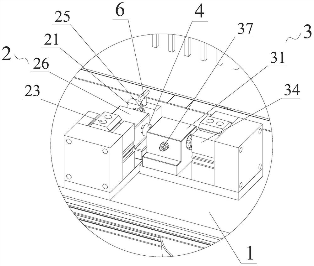
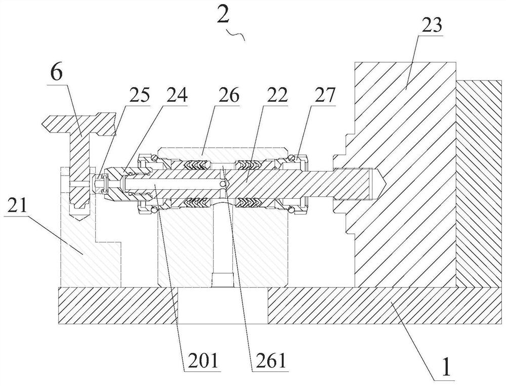
[0026] see Figure 1-4 As shown, a high-pressure fluid nozzle detection workbench includes a detection table 1, and the detection table 1 is provided with a nozzle detection and positioning assembly 2 and a high-pressure fluid on-off assembly 3, and the nozzle detection and positioning assembly 2 is connected to the A fluid delivery joint 4 is provided between the high-pressure fluid on-off components 3, a first fluid channel 201 is provided in the nozzle detection and positioning component 2, and a second fluid that can be controlled on and off is provided inside the high-pressure fluid on-off component 3. Channel 301, the high-pressure fluid on-off assembly 3 is connected to the small sprayer 5 arranged under the detection table 1 through a pipeline, and the nozzle detection and positioning assembly 2 is used to fix and communicate with the no...


PUM


Abstract

The invention provides a high-pressure fluid nozzle detection workbench, which comprises a nozzle detection positioning assembly and a high-pressure fluid on-off assembly which are arranged on a detection table, wherein a fluid conveying joint is arranged between the nozzle detection positioning assembly and the high-pressure fluid on-off assembly, a first fluid channel is arranged in the nozzle detection positioning assembly, the high-pressure fluid on-off assembly is internally provided with a second fluid channel capable of being controlled in an on-off mode, the high-pressure fluid on-off assembly is connected with a small spraying machine through a pipeline, the nozzle detection positioning assembly is used for fixing and communicating a to-be-detected nozzle part, a fluid pumped by the small spraying machine is conveyed to the to-be-detected nozzle part through the second fluid channel, the fluid conveying joint and the first fluid channel, a detection scale and a filter screen are arranged on the rear side of the detection table, and a liquid storage tank is arranged below the filter screen. According to the invention, the backward means of manual assembly detection in the past is changed, the production quality inspection process can be optimized, the working efficiency is improved, and the high-pressure fluid nozzle distinguishing detection level is greatly improved.

Description

technical field [0001] The invention relates to the technical field of airless spraying machine production detection, in particular to a high-pressure fluid nozzle detection workbench. Background technique [0002] The high-pressure fluid nozzle in the spraying machine, especially the airless spraying machine, is a key part of the equipment. At present, in the production and testing process of the high-pressure fluid nozzle, the product quality of the high-pressure fluid nozzle will be affected by factors such as the assembly process, the qualification rate of parts, etc. Many factors interfere, among which the problem of nozzle parts is the most prominent. In the past inspection process, there is no method that can effectively identify the qualification rate of the high-pressure fluid nozzle product itself. All high-pressure fluid nozzles need to be manually assembled to the finished spray gun, and then the actual injection test is carried out together with the spray gun. ...

Claims


Application Information

Patent Timeline
Patent Type & Authority Applications(China)
IPC IPC(8): G01M13/00
CPCG01M13/00
Inventor 赵志东黄胤杰潘文轩饶晨晖
Owner 福州赋达机电有限公司
Why Eureka
Eureka Blog
Learn More