
Novel cable stripper

A technology of wire stripper and cable, which is applied in the direction of cable installation, cable installation device, line/collector parts, etc. It can solve the problems of permanent damage to cables, low stripping efficiency, time-consuming and labor-intensive problems, etc.

Inactive Publication Date: 2021-05-11
于霞
View PDF0 Cites 0 Cited by
  • Summary
  • Abstract
  • Description
  • Claims
  • Application Information

AI Technical Summary

Problems solved by technology

[0003] The existing wire stripping operation is generally carried out manually. One is to use a utility knife to gradually cut the cable skin, and the stripping efficiency is extremely low. In addition, there is also a cable stripper, which is manually rotated Cutting, in the process of operation, due to the inability to control the force, a little careless excessive force will cause permanent damage to the cable, and it is necessary to re-make the cable head after cutting, both of which are time-consuming and labor-intensive.

Method used


Image

  • Novel cable stripper
  • Novel cable stripper
  • Novel cable stripper

Examples


Embodiment Construction

[0028] The following will clearly and completely describe the technical solutions in the embodiments of the present invention with reference to the accompanying drawings in the embodiments of the present invention. Obviously, the described embodiments are only some, not all, embodiments of the present invention.

[0029] In describing the present invention, it should be understood that the terms "upper", "lower", "front", "rear", "left", "right", "top", "bottom", "inner", " The orientation or positional relationship indicated by "outside", etc. is based on the orientation or positional relationship shown in the drawings, and is only for the convenience of describing the present invention and simplifying the description, rather than indicating or implying that the referred device or element must have a specific orientation, so as to Specific orientation configurations and operations, therefore, are not to be construed as limitations on the invention.

[0030] refer to Figure ...


PUM


Abstract

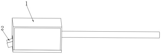
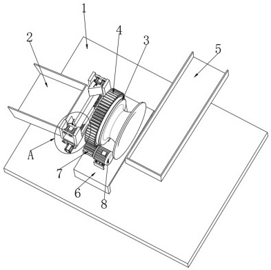
The invention discloses a novel cable stripper. The cable stripper comprises a box body, a mounting frame is fixedly arranged on the side wall of the bottom in the box body, a horn-shaped sleeve seat is fixedly connected to the side wall of the center of the mounting frame, and a driven gear is rotationally connected to the outer side of the sleeve seat. A first driving motor is fixedly connected to the upper side of the mounting frame through a support, the driving shaft of the first driving motor is fixedly connected with a driving gear, the driving gear is meshed with a driven gear, two L-shaped fixing rods are symmetrically and fixedly connected to the side wall of one end of the driven gear, and a distance adjusting device is connected between the two L-shaped fixing rods. Two U-shaped frames are symmetrically arranged on the distance adjusting device, and the distance adjusting device can drive the two U-shaped frames to move towards each other or away from each other. The invention relates to the technical field of power auxiliary equipment. The cable stripper can smoothly and stably cut off the skin of a cable, effectively prevents a cutter from damaging an internal cable metal wire, and is time-saving and labor-saving.

Description

technical field [0001] The invention relates to the technical field of electric power auxiliary equipment, in particular to a novel cable stripper. Background technique [0002] At present, with the rapid development of the economy, the urban power grid is also developing rapidly, and the demand for power and communication engineering equipment is also gradually increasing. During the construction of power equipment, a large number of cables need to be laid, and the cable terminals need to be stripped to connect the terminals. . [0003] The existing wire stripping operation is generally carried out manually. One is to use a utility knife to gradually cut the cable skin, and the stripping efficiency is extremely low. In addition, there is also a cable stripper, which is manually rotated Cutting, in the process of operation, due to the inability to control the strength, a little careless excessive force will cause permanent damage to the cable, and it is necessary to re-make...

Claims


Application Information

Patent Timeline
IPC IPC(8): H02G1/12H01R43/28B08B1/00B08B1/02B08B15/04
CPCH02G1/1248H02G1/1265H02G1/127H01R43/28B08B15/04B08B1/20B08B1/165
Inventor 于霞田金林
Owner 于霞
Learn More