Single-stator single-rotor dual-system low-pulsating-torque permanent magnet brushless motor and driving method

A technology of permanent magnet brushless motor and pulsating torque, which is applied in the direction of torque pulsation control, magnetic circuit rotating parts, magnetic circuit, etc., which can solve the problems of increased manufacturing cost, complex motor structure, and application in low-power applications , to achieve the effect of offset suppression and reduction of ripple torque

Pending Publication Date: 2021-05-11
HANGZHOU DIANZI UNIV
View PDF1 Cites 0 Cited by
  • Summary
  • Abstract
  • Description
  • Claims
  • Application Information

AI Technical Summary

Problems solved by technology

[0003] Patent No. "CN 105449958 B" patent "a brushless motor system with low pulsating torque" proposes a permanent magnet brushless motor with low pulsating torque based on double stators and double rotors. The permanent magnet brushless motor provides an effective solution for the permanent magnet brushless motor with low pulsating torque, and it has been proved by experiments that it has a good effect of suppressing pulsating torque, but due to the double stator and double rotor structure, The structure of the motor is relatively complicated, the volume increases, and the manufacturing cost increases, which affects its application in low-power occasions
Moreover, the double-stator double-rotor structure will cause the electromagnetic parameters of the two systems to be different due to technological problems, so that the mutual suppression effect of the two pulsating torques will be affected to a certain extent.

Method used


Image

  • Single-stator single-rotor dual-system low-pulsating-torque permanent magnet brushless motor and driving method
  • Single-stator single-rotor dual-system low-pulsating-torque permanent magnet brushless motor and driving method
  • Single-stator single-rotor dual-system low-pulsating-torque permanent magnet brushless motor and driving method

Examples


preparation example Construction

[0039] The preparation process of the low pulsating torque permanent magnet brushless DC motor is as follows:

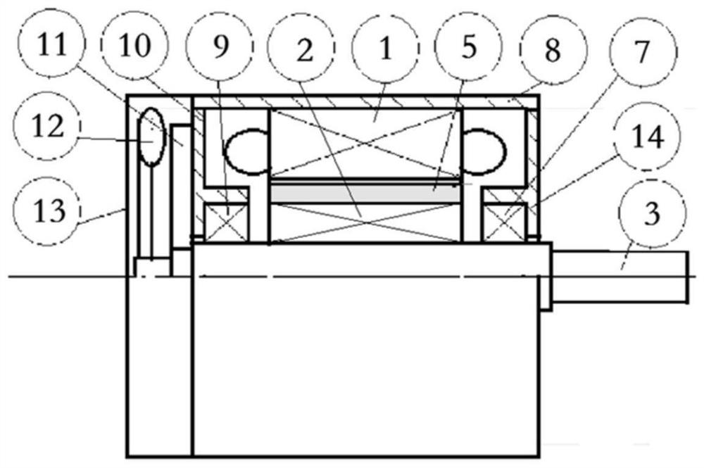
[0040] First process the stator core 1, the first winding group 4, the second winding group 6, the rotor core 2, the permanent magnetic steel 5, the central shaft 3, the front end cover 14, the front end cover bearing 7, the frame 8, and the rear end cover Bearing 9, rear end cover 10, position sensor 11, cooling fan 12 and fan cover 13.

[0041] Then install and assemble, specifically as follows: install the first winding group 4 and the second winding group 6 in the winding slots of the stator core 1 respectively, fix the stator with the windings in the frame 8, and install the two winding groups The lead-out line of the lead-out line is drawn out of the frame; the rotor core 2 is fixedly installed on the central shaft 3; the permanent magnetic steel 5 is fixed on the rotor core 2; the front end cover bearing 7 and the rear end cover bearing 9 are respectively embe...

Embodiment 2

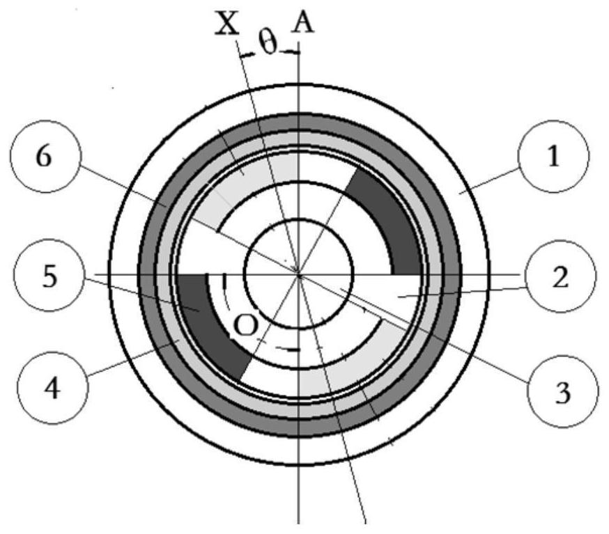
[0048] Such as image 3 As shown, the difference between this embodiment and Embodiment 1 is that the first winding group is evenly distributed along the inner side of the stator, accounting for 1 / 2 of the number of stator slots, and the number of pole pairs formed by the winding is the same as that of the rotor pole pairs. The winding groups are evenly distributed along the inner side of the stator. The electromagnetic parameters of the first winding group and the second winding group are the same. The two winding groups each account for 1 / 2 of the number of stator slots. The slots and the respective winding axes of the second winding group are offset by a certain angle θ from the corresponding winding axes of the first winding group, θ=360° / (4mn).

Embodiment 3

[0050] Such as Figure 7 As shown, the difference between this embodiment and Embodiment 1 is that: the pair of NS poles of the first winding group and the pair of NS poles of the second winding group are arranged adjacent to each other along the winding slots of the stator core, and in the first winding group The corresponding winding axis and the corresponding winding axis in the second winding group are staggered along the circumferential direction of the stator core or space angle. θ=360° / (4mn).

[0051] Such as Figure 4 and Figure 6 As shown, the first winding group and the second winding group each occupy 1 / 2 intervals in the tooth slots inside the stator core, and are evenly arranged in the respective interval slots to form m-phase symmetrical windings. The axis of the windings of the first winding group The axes of the corresponding windings of the second winding group are staggered by a space angle of 180°+θ or 180°-θ along the circumferential direction of th...


PUM


Abstract

The invention discloses a single-stator single-rotor dual-system low-pulsating-torque permanent magnet brushless motor and a driving method. The motor comprises a base, a stator core, a first winding, a second winding, permanent magnet steel, a rotor core and a rotating shaft, wherein the stator core is fixed on the inner side of the base. The rotor core is fixed on the rotating shaft, and the permanent magnet steel is fixed on the rotor iron core and located on the inner side of the stator core. The axis of the first winding and the axis of the second winding are staggered by a certain angle, and the first winding group and the second winding group are controlled to be powered on and powered off and the current direction according to a certain sequence under the control of the rotor position sensor and the controller. Current of the first winding set and current of the second winding set interact with the permanent magnet rotor to generate two pulsating torques which are similar in amplitude, identical in frequency and 180-degree in phase difference, offset suppression is achieved, the two generated average torques are identical in direction and size and are mutually overlapped to be output outwards, and pulsating torque components in the output torques are obviously reduced.

Description

technical field [0001] The invention belongs to the technical field of permanent magnet brushless motors, in particular to a single-stator single-rotor dual-system low-pulsation torque permanent magnet brushless motor and a driving method thereof. Background technique [0002] As a new type of speed-regulating motor, permanent magnet brushless DC motor is widely used in industry, agriculture, military, automobile, Home appliances and other fields. However, since its operation depends on the electronic commutation of the winding current, such as Figure 9 As shown, in the commutation process, the current of the motor in the commutation process fluctuates due to the time it takes for the current of the off-phase winding to drop from a stable value to zero and the time for the current of the on-phase winding to rise from zero to a stable value. The torque ripple changes. The torque ripple of the permanent magnet brushless DC motor is mainly the ripple torque component generate...

Claims


Application Information

Patent Timeline
IPC IPC(8): H02K29/03H02K1/27H02K3/12H02K3/28H02K11/22H02K9/06H02P6/10
CPCH02K29/03H02K1/2706H02K3/12H02K3/28H02K11/22H02K9/06H02P6/10H02K2213/03
Inventor 冯浩赵浩
Owner HANGZHOU DIANZI UNIV
Why Eureka
Try Eureka