Three-phase switched reluctance motor stator structure, corresponding motor and driving method

A reluctance motor and three-phase switch technology, applied in the direction of magnetic circuit shape/style/structure, structural connection, electric components, etc., can solve problems such as increasing the use cost of switched reluctance motors, affecting the wide application of motors, and complicated control

Pending Publication Date: 2020-10-23
HANGZHOU DIANZI UNIV
View PDF0 Cites 0 Cited by
  • Summary
  • Abstract
  • Description
  • Claims
  • Application Information

AI Technical Summary

Problems solved by technology

In severe cases, the pulsating torque can reach about 25% of the rated torque. Therefore, the motor will produce obvious vibration and noise during operation, which will affect the further extensive application of the motor in other fields.
[0003] In order to reduce the pulsating torque of the switched reluctance motor, the patent "A low pulsating torque switched reluctance motor and its driving method" with the application number "201911229568X" provides a method by setting double windings and using two speed regulation The control sy

Method used


Image

  • Three-phase switched reluctance motor stator structure, corresponding motor and driving method
  • Three-phase switched reluctance motor stator structure, corresponding motor and driving method
  • Three-phase switched reluctance motor stator structure, corresponding motor and driving method

Examples


Example Embodiment

[0033] Example 1

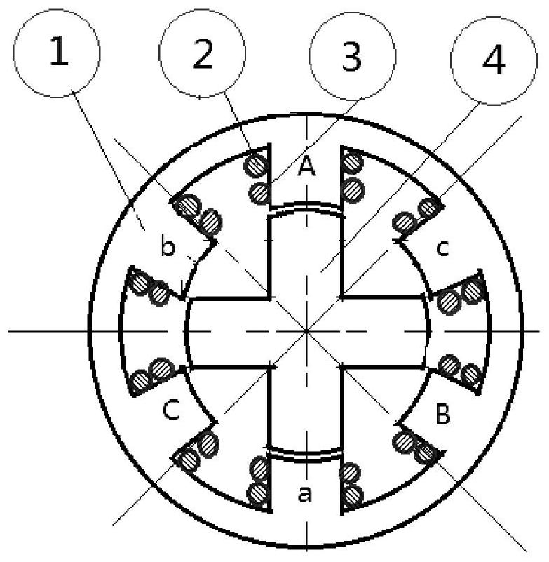
[0034] like figure 2 As shown, a stator structure of a three-phase switched reluctance motor includes a stator core 1 and a new three-phase winding. The number of pole pairs of the stator core 1 is 1, and has six slots evenly distributed along its circumferential direction. The three-phase winding includes six first coils 2 and six second coils 3 (twelve winding coils in total). A first coil 2 and a second coil 3 which are independent of each other are wound on the six slots of the stator core 1 . The parameters of the first coil 2 and the second coil 3 are the same. The parameters of the coil include the number of turns, material and wire diameter; the six slots of the stator core 1 are respectively defined as teeth A, teeth B, teeth C, teeth a, teeth b, and teeth c. The A tooth is set opposite to the a tooth; the B tooth is set opposite to the b tooth; and the C tooth is set opposite to the c tooth. A pole, B pole, and C pole have a 120° electrical a...

Example Embodiment

[0043] Example 2

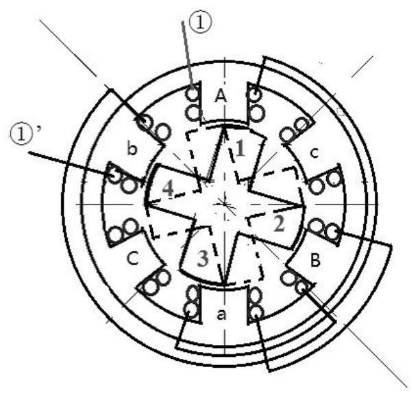
[0044] A stator structure of a three-phase switched reluctance motor. The difference between this embodiment and Embodiment 1 is that the number of pole pairs of the stator core 1 is n, and the number of pole pairs n≥2. The stator core 1 has 6n tooth slots uniformly distributed along its circumferential direction. The 6n slots are equally divided into n groups; the 6 slots in the same group are evenly distributed along the circumferential direction of the stator core 1 . The n groups of alveoli are sequentially staggered by 60° / n. The 6 slots of the same group are wound with three-phase windings according to the description in Embodiment 1. The windings of the same phase on n sets of cogging slots are connected in series (that is, on n sets of cogging slots, ①-①’ windings are connected in series, ②-②’ windings are connected in series, and ③-③’ windings are connected in series).

Example Embodiment

[0045] Example 3

[0046] like Figure 4 As shown, a three-phase low-pulsation torque switched reluctance motor includes a stator structure, a rotor core 4, a rotating shaft 5, a front end cover 6, a front end cover bearing 7, a frame 8, a rear end cover bearing 9, and a rear end cover 10. Position sensor 11, cooling fan 12, fan cover 13 and speed control system. The stator structure adopts a three-phase switched reluctance motor stator structure described in Embodiment 1 or 2. The two ends of the front end cover 6, the rear end cover 10 and the machine base 8 are respectively fixed. The outer rings of the front end cover bearing 7 and the rear end cover bearing 9 are respectively embedded in the middle parts of the inner surfaces of the front end cover 6 and the rear end cover 10 . Both ends of the rotating shaft 5 are respectively embedded in the inner rings of the front end cover bearing 7 and the rear end cover bearing 9 . The stator core 1 in the stator structure is f...


PUM


Abstract

The invention discloses a three-phase switched reluctance motor stator structure, a corresponding motor and a driving method. For an existing switched reluctance motor, due to a working principle, obvious pulsating torque exists in output torque of the motor. According to the invention, the stator structure comprises a stator core and three-phase windings, the three-phase windings are divided intoa (1)-(1)' winding, a (2)-(2)' winding and a (3)-(3)' winding. The (1)-(1)'winding is formed by sequentially connecting a first coil on the tooth A, a first coil on the tooth a, a first coil on the tooth B and a first coil on the tooth b in series. And the (2)-(2)' winding is formed by sequentially connecting a second coil on the B tooth, a second coil on the b tooth, a second coil on the C toothand a second coil on the c tooth in series. And the (3)-(3)' winding is formed by sequentially connecting a first coil on the C tooth, a first coil on the c tooth, a second coil on the A tooth and asecond coil on the a tooth in series. The electromagnetic torque generated by each phase of the rotor core has the torque characteristic of flat top waves, so that the purpose of effectively reducingthe pulsating torque is achieved.

Description

technical field [0001] The invention belongs to the technical field of switched reluctance motors, and in particular relates to a stator structure of a three-phase switched reluctance motor, a corresponding motor and a driving method. Background technique [0002] As a speed-regulating motor based on reluctance torque, switched reluctance motor has been widely used in mines, oil fields, textiles, automobiles and other fields due to its simple and firm structure, convenient speed regulation, reliable operation, and high efficiency. However, due to the working principle of the current switched reluctance motor, there is an obvious pulsating torque in the output torque of the motor. The three-phase switched reluctance motor is the most widely used switched reluctance motor. The waveform of the pulsating torque is similar to that of a sine waves are similar, specifically as figure 1 shown. In severe cases, the pulsating torque can reach about 25% of the rated torque. Therefore...

Claims


Application Information

Patent Timeline
IPC IPC(8): H02K1/14H02K3/18H02K3/28H02K11/22H02P25/098
CPCH02K1/146H02K3/18H02K3/28H02K11/22H02P25/098
Inventor 冯浩赵浩鲁俊
Owner HANGZHOU DIANZI UNIV
Why Eureka
Try Eureka