Motor stator for blood pump and motor for magnetic liquid levitation blood pump

A technology for motor stators and motors, applied in blood pumps, magnetic circuit shape/style/structure, electromechanical devices, etc., can solve the problems of large space occupation, low work efficiency, large motor size and weight, etc., and achieve small space occupation , light weight, and the effect of reducing ripple torque

Active Publication Date: 2019-01-25
HANGTIANTAIXIN TECH CO LTD
View PDF5 Cites 0 Cited by
  • Summary
  • Abstract
  • Description
  • Claims
  • Application Information

AI Technical Summary

Problems solved by technology

The above-mentioned radial magnetic field motor stator with slots will make the size and weight of the motor larger, occupy more space and have low work efficiency, and cannot meet the needs of the new type of magnetic fluid levitation centrifugal artificial assisted heart for the motor stator.
In addition, slots are opened on the stator core. Since there is a certain distance between the slots and the way the rotor cuts the magnetic field lines is limited, a relatively obvious pulsating torque will be generated during the rotation of the rotor. This pulsating torque is not Conducive to the stability of the rotor operation

Method used


Image

  • Motor stator for blood pump and motor for magnetic liquid levitation blood pump
  • Motor stator for blood pump and motor for magnetic liquid levitation blood pump
  • Motor stator for blood pump and motor for magnetic liquid levitation blood pump

Examples


Embodiment 1

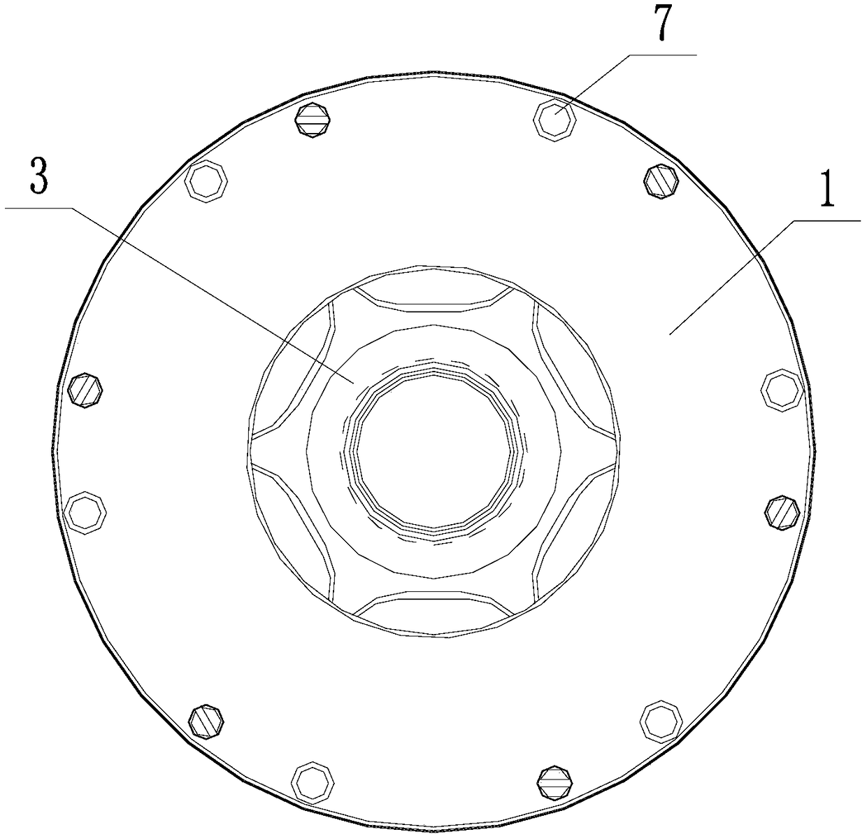
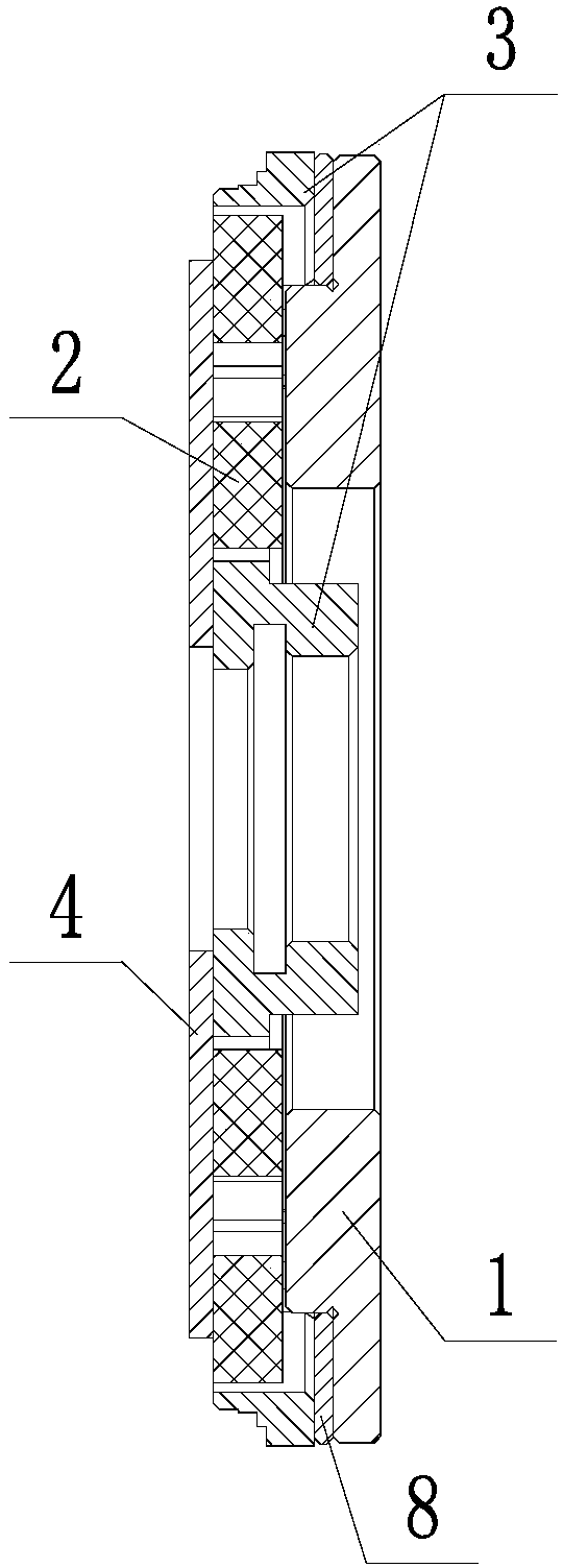
[0030] Such as figure 1 with 2 As shown, the blood pump motor stator provided in the first embodiment includes a stator core 1 , a stator bracket 3 , spacers 4 and six stator windings 2 . see figure 2 , the stator core 1 is fixed on the right side of the stator bracket 3 by screws 7, the spacer 4 is fixedly connected to the left side of the stator bracket 3, the way of fixed connection is preferably bonding, and the spacer 4 is used for liquid and The blood pump is separated from other structures by the motor stator, and for the magnetic fluid levitation centrifugal type artificial assisted heart, the liquid refers to blood. The stator support 3, spacer 4 and stator core 1 enclose a flat columnar space, roughly shaped as a cylinder with a small height, and the six stator windings 2 are arranged in a circular array and fixed inside the flat columnar space for supplying blood. The pump motor provides the electromagnetic field. A part of the stator core 1 is inserted into th...

Embodiment 2

[0043] The present invention provides a magnetic liquid levitation blood pump motor, which includes a motor rotor and two of the aforementioned blood pump motor stators, and the blood pump motor rotor is located in the liquid between the two blood pump motor stators to form a redundant The mechanism can further improve the reliability and stability of the blood pump motor, and is especially suitable for the blood pump motor in the magnetic liquid levitation centrifugal type artificial assisted heart.

[0044] Further, the motor for the magnetic liquid levitation blood pump also includes an upper pump casing and a lower pump casing, and two stators are symmetrically distributed and fixed on the upper pump casing and the lower pump casing respectively.


PUM


Abstract

The invention discloses a motor stator for a blood pump and belongs to the motor field. The motor stator for the blood pump comprises a stator core, a plurality of stator windings, a stator bracket and an isolation sheet; the stator core is detachably connected with one side surface of the stator bracket; the isolation sheet is fixedly connected with the other side surface of the stator bracket; the stator bracket, the isolation sheet and the stator core enclose a flat columnar space; the plurality of stator windings are fixed in the flat columnar space; and one part of the stator core is inserted into the stator bracket and contacts with the plurality of stator windings. The invention also discloses a motor for a magnetic liquid suspension type blood pump. The motor comprises two above motor stators for the blood pump. The motor stator for the blood pump provided by the invention is flat in shape and compact in structure, and just occupies a small space. The motor stator for the blood pump is suitable for a magnetic liquid suspension type centrifugal artificial assist heart.

Description

technical field [0001] The present invention relates to the field of motors, and more specifically, to a blood pump motor stator and a magnetic fluid levitation blood pump motor equipped with the blood pump motor stator. Background technique [0002] Micro motors are widely used in aerospace, medical equipment and other fields. In some applications, there are strict requirements on performance indicators such as the size, weight, temperature rise and operation reliability of the motor. For example, artificial heart assist has strict requirements on the shape, structure and space occupied by the motor. Require. [0003] Most of the existing artificial assisted heart motors are traditional radial field motors, and their motor stators are mostly cylindrical, and usually consist of a stator core and windings wound on the stator core. This structure needs to be fixed on the stator core. Slots are opened so that the windings can be embedded in the stator core, thereby achieving ...

Claims


Application Information

Patent Timeline
Patent Type & Authority Patents(China)
IPC IPC(8): H02K1/12H02K1/18H02K16/04A61M1/12
CPCA61M60/148A61M60/205H02K1/12H02K1/18H02K16/04
Inventor 苏静静王伟李冀鹏王博张磊
Owner HANGTIANTAIXIN TECH CO LTD
Why Eureka
Try Eureka