Switched reluctance motor with low ripple torque

A technology of pulsating torque and switched reluctance, which is applied in the field of motors, can solve the problems of large torque pulsation and restrictions on promotion and use, and achieve the effects of reducing torque pulsation, low dependence, and reducing pulsating torque

Active Publication Date: 2019-08-13
HANGZHOU DIANZI UNIV
View PDF3 Cites 0 Cited by
  • Summary
  • Abstract
  • Description
  • Claims
  • Application Information

AI Technical Summary

Problems solved by technology

[0002] The switched reluctance motor speed control system is one of the new motors with great development potential due to its simple structure, firmness, reliable operation, low cost, flexible system control, good speed regulation performance, high operating efficiency, and low temperature rise. One, but the torque ripple is large when the switched reluctance motor is running, usually the typical value of the torque ripple is 15%. The noise problem caused by the torque ripple and the resonance problem at a specific frequency are more prominent. Therefore, the switched reluctance motor In addition to certain applications in some general industries (fans, pumps, compressors, etc.), traction motors, and high-speed motors (textile machines, aero engines, centrifuges, etc.), it is popularized in some occasions that require high control and vibration noise. limited use

Method used


Image

  • Switched reluctance motor with low ripple torque
  • Switched reluctance motor with low ripple torque
  • Switched reluctance motor with low ripple torque

Examples


Embodiment 1

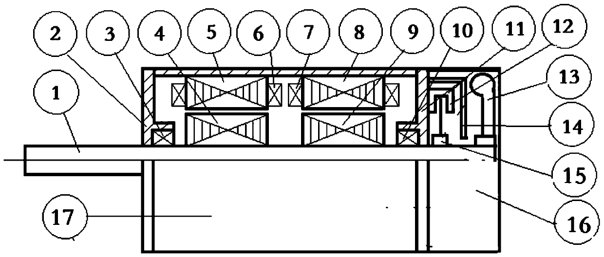
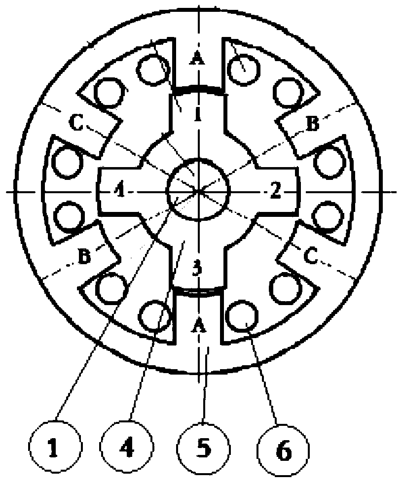
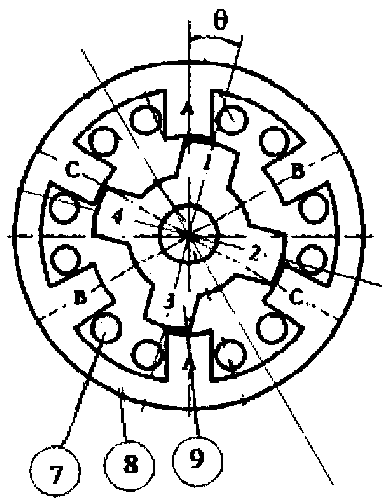
[0032] Projections of the first stator core 5 and the second stator core 8 on a plane perpendicular to the axis of the rotating shaft 1 completely coincide. The first rotor core 4 and the second rotor core 9 are arranged at an angle θ staggered along the circumferential direction of the rotating shaft 1 .

[0033]

[0034] The reason why the first rotor core 4 and the second rotor core 9 are staggered by the angle θ along the circumferential direction of the rotating shaft 1 is as follows:

[0035] The pulsating torque wave generated by the switched reluctance motor is similar to a sine wave, and every time the switched reluctance motor rotates a step angle, a period of pulsating torque wave will be generated at the same time. That is, the cycle of the pulsating torque of the switched reluctance motor is equal to the time period for the switched reluctance motor to rotate a step angle. The control period of the switched reluctance motor with the number of rotor iron core t...

Embodiment 2

[0038] The projections of the first rotor core 4 and the second rotor core 9 on a plane perpendicular to the axis of the rotating shaft 1 completely coincide. The first stator core 5 and the second stator core 8 are arranged at an angle θ staggered along the circumferential direction of the rotating shaft 1 .

[0039]


PUM


Abstract

The invention discloses a switched reluctance motor with low ripple torque. Due to the large pulsating torque of the switched reluctance motor, its popularization and use in some occasions with high requirements for control and vibration and noise are restricted. The invention includes a rotating shaft, a front end cover, a first sub-motor system, a second sub-motor system, a machine base and a rear end cover; the head end of the machine base is fixed to the front end cover, and the tail end is fixed to the rear end cover. The rotating shaft is supported on the front end cover and the rear end cover. The power, the number of phases and the number of pole pairs of the first sub-motor system and the second sub-motor system are the same. The projections of the stator core of the first sub-motor system and the stator core of the second sub-motor system on a plane perpendicular to the axis of the rotating shaft coincide completely. The rotor core of the first sub-motor system and the rotor core of the second sub-motor system are arranged at an angle θ staggered along the circumferential direction of the rotating shaft. The invention reduces the torque ripple of the switched reluctance motor, so that the switched reluctance motor can be applied to occasions with high vibration and noise requirements.

Description

technical field [0001] The invention belongs to the technical field of motors, in particular to a low-pulsation torque switched reluctance motor. Background technique [0002] The switched reluctance motor speed control system is one of the new motors with great development potential due to its simple structure, firmness, reliable operation, low cost, flexible system control, good speed regulation performance, high operating efficiency, and low temperature rise. One, but the torque ripple is large when the switched reluctance motor is running, usually the typical value of the torque ripple is 15%. The noise problem caused by the torque ripple and the resonance problem at a specific frequency are more prominent. Therefore, the switched reluctance motor In addition to certain applications in some general industries (fans, pumps, compressors, etc.), traction motors, and high-speed motors (textile machines, aero engines, centrifuges, etc.), it is popularized in some occasions th...

Claims


Application Information

Patent Timeline
Patent Type & Authority Patents(China)
IPC IPC(8): H02K16/00H02K29/03H02K29/10
CPCH02K16/00H02K29/03H02K29/10H02K2213/03
Inventor 冯浩王宁黎赵浩
Owner HANGZHOU DIANZI UNIV
Why Eureka
Try Eureka