Low-pulsating-torque switched reluctance motor and driving method thereof

A pulsating torque and switched reluctance technology, applied in motor control, AC motor control, torque pulsation control, etc., can solve problems affecting the wide application of motors, and achieve the effect of reducing pulsating torque

Inactive Publication Date: 2020-04-10
HANGZHOU DIANZI UNIV
View PDF3 Cites 0 Cited by
  • Summary
  • Abstract
  • Description
  • Claims
  • Application Information

AI Technical Summary

Problems solved by technology

In severe cases, the pulsating torque can reach about 25% of the rated torque. Therefore, the motor will produce obvious vibration and noise during operation, which will affect the further extensive application of the motor in other fields.

Method used


Image

  • Low-pulsating-torque switched reluctance motor and driving method thereof
  • Low-pulsating-torque switched reluctance motor and driving method thereof
  • Low-pulsating-torque switched reluctance motor and driving method thereof

Examples


Embodiment 1

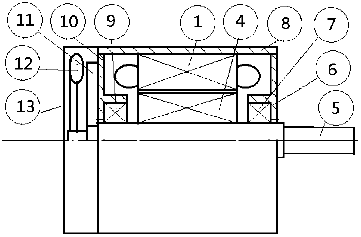
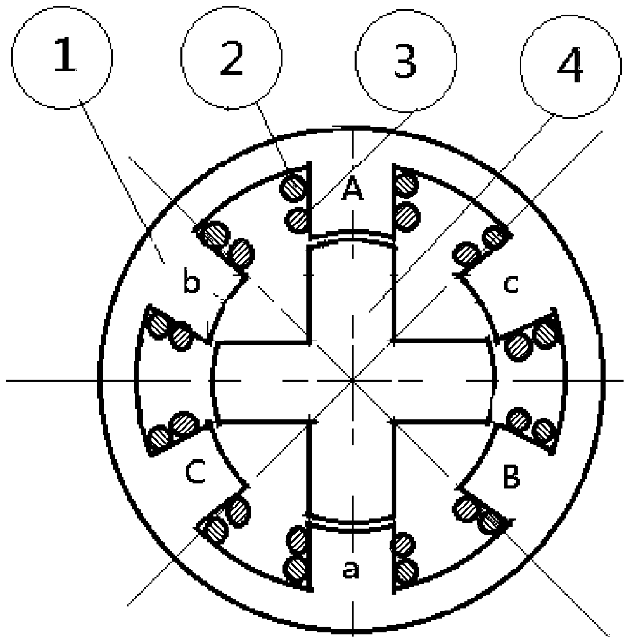
[0027] Such as figure 2 , 3 As shown in and 4, a switched reluctance motor with low pulsating torque includes a stator core 1, a first winding 2, a second winding 3, a rotor core 4, a rotating shaft 5, a front end cover 6, a front end cover bearing 7, and a base 8. Rear end cover bearing 9, rear end cover 10, position sensor 11, cooling fan 12, fan cover 13 and speed control system. The two ends of the front end cover 6, the rear end cover 10 and the machine base 8 are respectively fixed. The outer rings of the front end cover bearing 7 and the rear end cover bearing 9 are respectively embedded in the middle parts of the inner surfaces of the front end cover 6 and the rear end cover 10 . Both ends of the rotating shaft 5 are respectively embedded in the inner rings of the front end cover bearing 7 and the rear end cover bearing 9 . The stator core 1 is fixed inside the base 8 . The rotor core 4 is fixed on the rotating shaft 5 and located inside the stator core 1 . The r...

Embodiment 2

[0050] The difference between this embodiment and Embodiment 1 is that: the number of pole pairs of the stator core 1 and the rotor core 4 is n; n is not limited to 1. The tooth-to-slot ratio of the stator core 1 and the rotor core 4 (that is, the tooth ratio of the stator-rotor core) is 6n:4n. There are a total of 6n slots on the stator core 1 . The 6n alveoli are divided into n alveolar groups in groups of six. The six slots in the same slot group are evenly distributed along the circumferential direction of the central axis of the stator core 1 . The n slot groups are sequentially staggered along the circumferential direction of the central axis of the stator core 1

[0051] A first winding 2 and a second winding 3 are wound on each of the n slot groups of the stator core 1 . Both the first winding 2 and the second winding 3 are symmetrical three-phase windings with the same parameters. The 6 alveoli in the same group are respectively defined as tooth A, tooth B, toot...


PUM


Abstract

The invention discloses a low-pulsating-torque switched reluctance motor and a driving method thereof. Due to the working principle, obvious pulsating torque exists in the output torque of the switched reluctance motor. The motor comprises a base, a stator core, a first winding, a second winding, a rotor core and a rotating shaft, the rotating shaft is supported in the base, and the stator iron core is fixed at the inner side of the base. The rotor iron core is fixed on the rotating shaft and is located at the inner side of the stator iron core, and the first winding and the second winding are wound on the six tooth grooves of the stator iron core and are symmetrical three-phase windings. According to the invention, the first winding and the second winding respectively act on the electromagnetic average torque and the pulsating torque generated by the rotor core, the two average torque directions are the same, the driving load is outputted in a superposition manner, the phase difference of the two pulsating torques is 180 degrees, and the amplitudes of the two pulsating torques are close, and therefore the counteracting suppression can be effectively achieved after superposition,and the purpose of effectively reducing the pulsating torques is achieved.

Description

technical field [0001] The invention belongs to the technical field of switched reluctance motors, and in particular relates to a low-pulsation torque switched reluctance motor and a driving method thereof. Background technique [0002] As a speed-regulating motor based on reluctance torque, switched reluctance motor has been widely used in mines, oil fields, textiles, automobiles and other fields due to its simple and firm structure, convenient speed regulation, reliable operation, and high efficiency. However, due to the working principle of the current switched reluctance motor, there is an obvious pulsating torque in the output torque of the motor. The waveform of the pulsating torque is similar to a sine wave, specifically as figure 1 shown. In severe cases, the pulsating torque can reach about 25% of the rated torque. Therefore, the motor will produce obvious vibration and noise during operation, which will affect the further extensive application of the motor in oth...

Claims


Application Information

Patent Timeline
Patent Type & Authority Applications(China)
IPC IPC(8): H02K29/03H02K29/10H02P25/098H02P6/10
CPCH02K29/03H02K29/10H02K2213/03H02P6/10H02P25/098H02P2207/05
Inventor 冯浩赵浩丁立军
Owner HANGZHOU DIANZI UNIV
Why Eureka
Try Eureka