Atrial septum shunting device for treating heart failure

A shunt device and atrial septum technology, applied in the field of medical devices, can solve problems such as PCWP rise

Pending Publication Date: 2021-05-14
ENEIDE MEDICAL TECH SHANGHAI CO LTD
View PDF0 Cites 2 Cited by
  • Summary
  • Abstract
  • Description
  • Claims
  • Application Information

AI Technical Summary

Problems solved by technology

Retrospective data show that although the pulmonary capillary wedge pressu...

Method used


Image

  • Atrial septum shunting device for treating heart failure
  • Atrial septum shunting device for treating heart failure
  • Atrial septum shunting device for treating heart failure

Examples


Embodiment 1

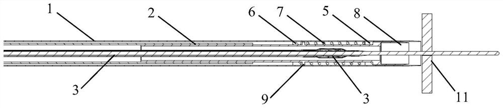
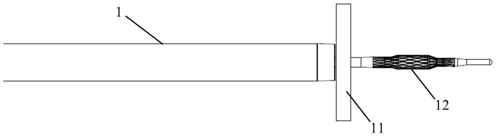
[0158] The atrial septal shunt device for treating heart failure in this embodiment is as follows: Figure 1-9 shown. The device includes an outer tube 1 , a cutter head delivery tube 2 , a fluid bag catheter 3 and an operating handle 4 .

[0159] The outer tube 1 is used as the outermost catheter, which is a hollow tube structure. A first stop ring 5 and a second stop ring 6 are provided at the far end of the inner cavity of the outer tube 1, wherein the first stop ring 5 is opposite to the first stop ring. The second stop ring 6 is arranged closer to the distal end.

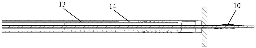
[0160] The cutter head delivery tube 2 is placed in the hollow inner cavity of the outer tube 1, and the cutter head delivery tube 2 is also a hollow tube. The cutter head delivery tube 2 comprises a proximal delivery tube 13 and a distal delivery tube 14, wherein the outer diameter of the proximal delivery tube 13 is less than the inner diameter of the outer tube 1, and the outer diameter of the distal deliv...

Embodiment 2

[0175] The atrial septal shunt device for treating heart failure in this embodiment is substantially the same as that of Embodiment 1, the difference is that the atrial septal shunt device in this embodiment is provided with an auxiliary fixing part 20, which is used to work together with the liquid bag 10 Clamp and fix interatrial septum. When in use, the expanded liquid bag 10 abuts against one side of the atrial septum of the heart, and the auxiliary fixing part 20 abuts against the other side of the atrial septum of the heart, and its position corresponds to that of the liquid bag 10. Fix the wall surface of the cardiac interatrial septum to be perforated so as to facilitate the perforation operation by the cutting head 8 .

[0176] The auxiliary fixing part 20 of this embodiment is located between the outer tube 1 and the distal delivery tube 14 , and is disposed close to the distal delivery tube 14 . The auxiliary fixing part 20 is annular, its proximal end is fixed on ...

Embodiment 3

[0179] The atrial septal shunt device for treating heart failure in this embodiment is substantially the same as that in Embodiment 2, the difference is that the atrial septal shunt device in this embodiment is provided with an auxiliary fixing part 20 which is an independent structure, such as Figure 14 As shown, it is located in the lumen of the cutter head delivery tube 2, and advances or retracts in the lumen. The auxiliary fixing part 20 of this embodiment includes an auxiliary fixing catheter 22 and an auxiliary fixing head 23, and the liquid bladder catheter 3 is located in the lumen of the auxiliary fixing catheter 22, that is, the auxiliary fixing catheter 22 is located between the knife head delivery tube 2 and the liquid bladder catheter 3. Among them, the auxiliary fixing catheter 22 is located in the lumen of the proximal delivery tube 13 and the distal delivery tube 14 , and the auxiliary fixing head 23 is located in the cavity of the annular cutting head 8 . Th...


PUM


Abstract

The invention discloses an atrial septum shunting device for treating heart failure, which comprises an outer tube, the outer tube being a hollow tube, a first stop block and a second stop block being arranged at the far end of the inner cavity of the outer tube, and a spring being arranged between the first stop block and the second stop block; a tool bit conveying pipe, arranged in the hollow inner cavity of the outer pipe, the tool bit conveying pipe being also a hollow pipe, a cutting tool bit being arranged at the farthest end of the tool bit conveying pipe, a protruding part being arranged on the periphery of the tool bit conveying pipe, and the protruding part being located between the second stop block and the spring; a liquid bag catheter, arranged in the hollow inner cavity of the scalpel head conveying pipe, and a liquid bag being arranged on the liquid bag catheter; and an operating handle, the near end of the outer tube, the near end of the cutter head conveying tube and the near end of the liquid bag catheter being fixedly connected to the operating handle. According to the device, after expansion, the liquid bag and the support abut against one side of the atrial septum, the cutting tool bit cuts in from the other side of the atrial septum, a hole is punched in the position of the atrial septum, and then heart failure is effectively treated.

Description

technical field [0001] The invention relates to the field of medical devices, in particular to an atrial septal shunt device for treating heart failure. Background technique [0002] Heart failure (heart failure) is the final result of various cardiovascular events and the cumulative effect of various cardiac abnormalities, which ultimately leads to a decline in the pumping function of the heart. Once the clinical manifestations of heart failure appear in cardiovascular patients, the prognosis is poor. The more severe the heart failure, the higher the risk of death. Heart failure is a group of complex clinical syndromes caused by abnormal changes in the structure and function of the heart caused by various reasons. difficulty, fatigue) and fluid retention (pulmonary congestion, systemic congestion, and peripheral edema). [0003] Heart failure with preserved ejection fraction (HFpEF, LVEF value ≥ 50%) is a common type of heart failure, accounting for about 50% of heart fa...

Claims


Application Information

Patent Timeline
IPC IPC(8): A61B17/00A61B17/3205A61M29/04
CPCA61B17/00A61B17/32053A61M29/02
Inventor 沈碧峰朱大伟洪炯龚瑜
Owner ENEIDE MEDICAL TECH SHANGHAI CO LTD
Why Eureka
Try Eureka