
Concrete mixing device for constructional engineering

A technology for construction engineering and mixing devices, which is applied in the direction of unloading devices, clay preparation devices, and sales of raw material supply devices, etc. It can solve the problems of low mixing efficiency, lack of control of mixing ratio, and single mixing method.

Active Publication Date: 2021-05-14
山东中岩重科新材料科技有限公司
View PDF7 Cites 6 Cited by
  • Summary
  • Abstract
  • Description
  • Claims
  • Application Information

AI Technical Summary

Problems solved by technology

[0003] In the process of concrete preparation, various raw materials need to be fully mixed according to a certain proportion. Therefore, the main factors that determine the quality of concrete are the proportion of concrete materials and the degree of mixing. However, most of the existing concrete mixing devices only have the function of mixing. , does not have the function of controlling the mixing ratio, and often needs to be controlled by other equipment, and the mixing method of the traditional concrete mixing device is relatively simple, and it often takes a long time to mix to achieve the ideal mixing degree, thus making the mixing efficiency low profile, highlighting the shortcomings of conventional concrete mixers

Method used


Image

  • Concrete mixing device for constructional engineering
  • Concrete mixing device for constructional engineering
  • Concrete mixing device for constructional engineering

Examples


Embodiment Construction

[0024] The present invention will be further elaborated below in conjunction with the accompanying drawings and specific embodiments.

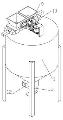
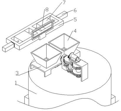
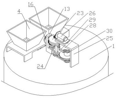
[0025] like Figure 1-9 As shown, a concrete mixing device for construction engineering includes a barrel body 1, support legs 2, sliding support groove 3, feeding hopper 4, sliding frame 5, No. 1 push rod motor 6, adjusting partition 7, rack Frame 8, transmission part 9, power part 10, stirring part 11, control part 12, a plurality of vertical support legs 2 are fixed at the bottom of the barrel body 1, and a horizontal sliding support groove 3 is fixed at the top of the barrel body 1 Two vertical feeding hoppers 4 are fixed on the top of the sliding support groove 3, a vertical opening runs through the bucket body 1 below the middle part of the sliding supporting groove 3, and a horizontal opening is slidably connected inside the sliding supporting groove 3. The sliding frame 5, the sliding frame 5 is "day" font, the front and rear ends of ...


PUM


Abstract

The invention discloses a concrete mixing device for constructional engineering. The concrete mixing device for constructional engineering comprises a barrel body, supporting legs, a sliding supporting groove, feeding hoppers, a sliding frame, a first push rod motor, adjusting partition plates, a rack frame, a transmission part, a power part, a stirring part and a control part, the plurality of vertical supporting legs are fixedly arranged at the bottom of the barrel body, the horizontal sliding supporting groove is fixedly arranged on the top end of the barrel body, the two vertical feeding hoppers are fixedly arranged on the top end of the sliding supporting groove, and a vertical opening is formed in a position, below the middle of the sliding supporting groove, of the barrel body in a penetrating mode. According to the concrete mixing device for constructional engineering, the purpose of adjusting the material mixing proportion can be achieved by adjusting the positions of the two adjusting partition plates in the sliding frame, a first reciprocating stirring paddle and a second reciprocating stirring paddle can horizontally move in a stirring barrel in a reciprocating mode through rolling friction between a first rolling wheel and the inner wall of the barrel body and between a second rolling wheel and the inner wall of the barrel body and between a protruding plate and the inner wall of the barrel body. and therefore, materials in the stirring barrel can be stirred more sufficiently.

Description

technical field [0001] The invention relates to a mixing device, in particular to a concrete mixing device for construction engineering. Background technique [0002] Ordinary concrete refers to the artificial stone made of cement as the main cementitious material, mixed with water, sand, stones, chemical admixtures and mineral admixtures when necessary, mixed in an appropriate proportion, and uniformly stirred, compacted and cured. . Concrete is mainly divided into two stages and states: the plastic state before setting and hardening, that is, fresh concrete or concrete mixture; the hard state after hardening, that is, hardened concrete or concrete. [0003] In the process of concrete preparation, various raw materials need to be fully mixed according to a certain proportion. Therefore, the main factors that determine the quality of concrete are the proportion of concrete materials and the degree of mixing. However, most of the existing concrete mixing devices only have th...

Claims


Application Information

Patent Timeline
IPC IPC(8): B28C5/16B28C5/32B28C7/06B28C7/16B08B9/087
CPCB28C5/16B28C7/16B28C7/06B28C5/325B08B9/087
Inventor 王硕
Owner 山东中岩重科新材料科技有限公司
Learn More