
Blind zone monitoring method and device, equipment and medium

A blind spot monitoring and blind spot technology, which is applied in signal devices, optical observation devices, transportation and packaging, etc., can solve the problems that the blind spot area of ​​the camera cannot be monitored, the driver of the vehicle cannot know in time, and the occurrence of traffic accidents, etc.

Active Publication Date: 2021-05-14
TIANJIN SOTEREA AUTOMOTIVE TECH LMITED CO +1
View PDF9 Cites 9 Cited by
  • Summary
  • Abstract
  • Description
  • Claims
  • Application Information

AI Technical Summary

Problems solved by technology

[0003] The camera of the blind spot detection system in the prior art is usually installed on the body panel near the rear of the vehicle to capture images of the blind spots on the side and front, resulting in that the blind spots directly below the camera and behind the side cannot be monitored, and there are pedestrians or vehicles in this area. When things happen, the driver of the vehicle cannot know in time, and it is easy to cause traffic accidents

Method used


Image

  • Blind zone monitoring method and device, equipment and medium
  • Blind zone monitoring method and device, equipment and medium
  • Blind zone monitoring method and device, equipment and medium

Examples


Embodiment Construction

[0033]In order to further illustrate the technical means and efficacy of the present invention to achieve the object of the present invention, the specific embodiment of a blind spot monitoring method and apparatus, apparatus, medium proposed in accordance with the present invention is intended in conjunction with the drawings and preferred embodiments. , Structural, characteristics, and effects, detailed description.

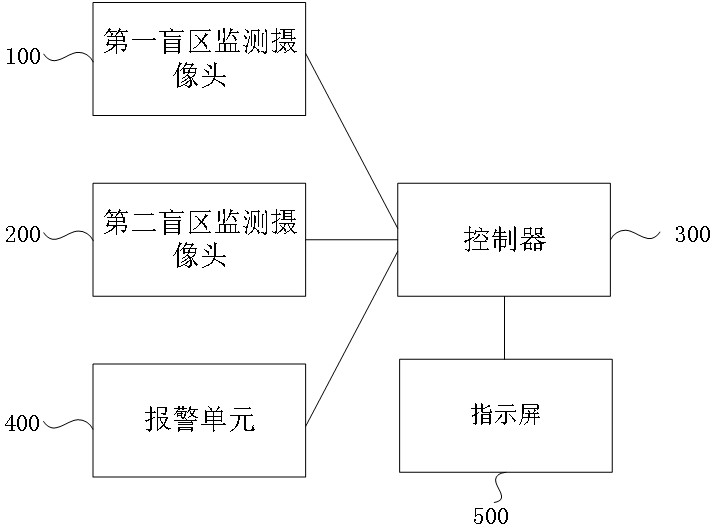
[0034]The embodiment of the present invention provides a blind spot monitoring device, including:

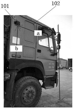
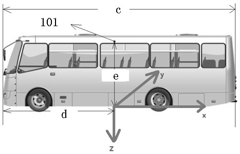
[0035]The first blind spot monitoring the camera and the second blind spot monitor the camera, along the vertical direction in the direction of the vehicle, the first blind zone monitoring camera and the second blind zone monitoring camera is mounted on the vehicle body plate opposite to the vehicle opposite sides; The viewing angle of the first blind spot monitoring camera and the second blind spot monitoring the camera is 150 °, and both relative to the pitch angle of the ...


PUM

PropertyMeasurementUnit
Installation heightaaaaaaaaaa

Abstract

The invention discloses a blind area monitoring method and device, equipment and a medium. The field angle of a first blind area monitoring camera and the field angle of a second blind area monitoring camera in the blind area monitoring device are both 150 degrees, and the pitch angles relative to a vehicle body are both located in a preset range, so that the shot blind area image takes the edge line of the vehicle body as the corresponding edge, and when the vehicle is a head-body separation type vehicle, the first blind area monitoring camera and the second blind area monitoring camera are both installed on a vehicle head of the vehicle, and the installation height of the first blind area monitoring camera and the installation height of the second blind area monitoring camera are lower than or equal to the installation height of rearview mirrors of the vehicle and higher than the preset height. When the vehicle is a head-body integrated vehicle, the first blind area monitoring camera and the second blind area monitoring camera are installed in the middle of a vehicle body on the corresponding side of the vehicle, and the installation height is higher than the upper edge of a vehicle window of the vehicle. According to the method provided by the embodiment of the invention, the applicability of the blind area monitoring device to different vehicle types is improved while a relatively large blind area monitoring range is ensured.

Description

Technical field[0001]Embodiments of the present invention relate to vehicle active safety techniques, and more particularly to a blind spot monitoring method and apparatus, apparatus, and media.Background technique[0002]Blind Spot Detection (BSD) system is a high-tech configuration on the automobile. The main function is to remove the rear view mirror blind area, detect the pedestrians in the rear view of the side of the vehicle by the camera, to the driver And pedestrians to remind, avoid accidents that occur due to pedestrians during the driving process.[0003]The casing of the blind spot detection system in the prior art is usually mounted on the position of the body plate near the tail, the blind zone image in front of the shooting side, causing the image of the camera and the blind zone area behind the side to monitor, the region has the target or vehicle. When the vehicle driver can't understand in time, there will be a traffic accident.Inventive content[0004]The present invent...

Claims


Application Information

Patent Timeline
IPC IPC(8): B60R1/00B60Q9/00
CPCB60Q9/008B60R1/00B60R2300/105B60R2300/802
Inventor 徐显杰亚瑟·菲利波维奇包永亮马玉珍高艳艳
Owner TIANJIN SOTEREA AUTOMOTIVE TECH LMITED CO
Learn More