A wind turbine tower life prediction method, system, equipment and storage medium

A life prediction and motor unit technology, which is applied to mechanical equipment, wind power generation, wind engines, etc., can solve the problems of inability to accurately and effectively predict and evaluate tower loads and life, and achieve the effects of avoiding equipment damage and high computing efficiency

Active Publication Date: 2022-03-22
HUANENG CLEAN ENERGY RES INST +1
View PDF9 Cites 0 Cited by
  • Summary
  • Abstract
  • Description
  • Claims
  • Application Information

AI Technical Summary

Problems solved by technology

[0008] The purpose of the present invention is to overcome the shortcomings in the above-mentioned prior art that the tower load and life cannot be accurately and effectively predicted and evaluated, and to provide a wind turbine tower life prediction method, system, equipment and storage medium

Method used


Image

  • A wind turbine tower life prediction method, system, equipment and storage medium
  • A wind turbine tower life prediction method, system, equipment and storage medium
  • A wind turbine tower life prediction method, system, equipment and storage medium

Examples


Embodiment 1

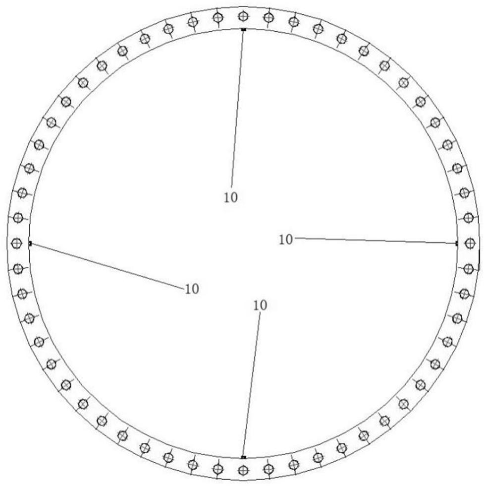
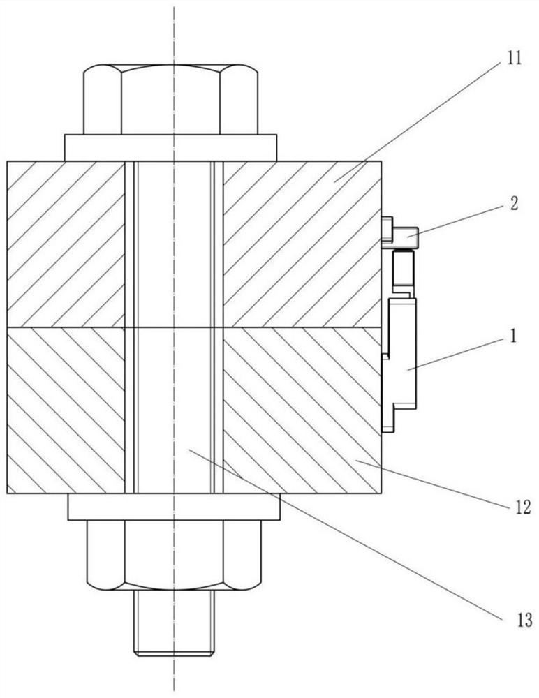
[0098] A wind turbine tower life prediction method, such as figure 1 and Figure 4 As shown, several connectors are installed on the tower body of the wind turbine. Figure 5 As shown, the connecting piece includes an upper flange 11 and a lower flange 12, bolts 13 are arranged on the upper flange 11 and lower flange 12, an upper gasket 14 is arranged between the upper flange 11 and the bolt 13, and the lower flange A lower gasket 15 is provided between 12 and the bolt 13 .

[0099] implementation of methods such as Figure 7 shown, including the following steps:

[0100] S1: measure the displacement data by the displacement sensor 10, and transmit the displacement data to the host computer for processing;

[0101] S2: Calculate the working load on each layer of flange based on the data processed by the host computer;

[0102] S3: Calculate the stress data of the flanges of each layer and related welds, and the ring section of the tower shell through the calculation of th...

Embodiment 2

[0105] Except for the following content, all the other contents are the same as in Example 1.

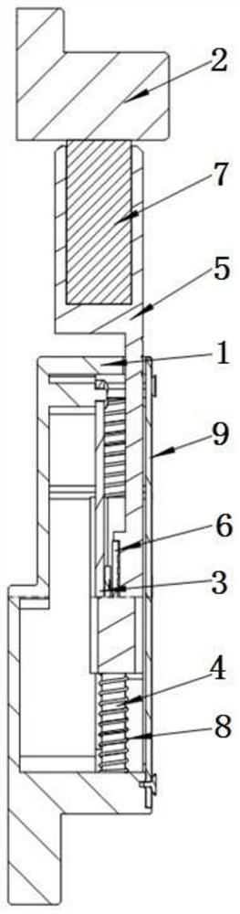
[0106] The displacement sensor 10 is a split type displacement sensor, and the displacement sensor 10 includes a limit block 2 and a displacement sensor body, and the limit block 2 and the displacement sensor body are respectively fixed on two interconnected connectors. The displacement sensor 10 is evenly installed on the inner or outer circumference of the flange connection, and the spacer 2 and the sensor body separated from each other in the displacement sensor 10 are respectively fixed on the two interconnected flanges.

Embodiment 3

[0108] A wind turbine tower life prediction method, such as figure 2 and image 3 shown, including the following steps:

[0109] S1. Evenly install the high-precision displacement sensor 10 on the inner or outer circumference of the flange connection, and fix the spacer 2 and the sensor body separated from each other in the high-precision displacement sensor 10 to the two interconnected flanges respectively. Lan Shang;

[0110] S2. When the tower is subjected to an external load, the axial relative displacement of the upper flange 11 and the lower flange 12 changes, and occurs between the limit block 2 installed on a pair of flanges and the sensor body (housing 1). Relative displacement, the magnet 6 on the high-precision displacement sensor 10 slides on the surface of the electromagnetic induction chip, the magnetic field around the high-precision electromagnetic induction chip changes linearly, the high-precision electromagnetic induction chip captures the change of the m...


PUM


Abstract

The invention discloses a method, system, equipment and storage medium for predicting the service life of a wind turbine tower, and belongs to the technical field of wind turbine monitoring. Monitor the axial relative displacement of the flange through the displacement sensor, analyze, count and warn the stress of the main parts of the tower and the consumed fatigue life value, and send an alarm message when the consumed fatigue life value of each main part of the tower reaches the set threshold , to provide a monitoring basis for the implementation of the tower safety control strategy. It can realize fully automatic processing, high calculation efficiency, real-time online monitoring of the fatigue life of each main part of the tower, and when the exhausted fatigue life of each main part of the tower reaches the set threshold, an alarm message will be sent to provide a guarantee for the implementation of the tower safety control strategy. Monitoring basis to avoid equipment damage due to excessive tower fatigue damage.

Description

technical field [0001] The invention belongs to the technical field of wind turbine monitoring, and relates to a wind turbine tower life prediction method, system, equipment and storage medium. Background technique [0002] Wind turbines are power generation equipment that require long-term operation. The explosive growth of wind power generation in recent years has brought huge challenges to the long-term safe and stable operation of wind turbines. The wind turbine is a device that drives the wind motor to rotate by the impeller against the wind, and converts wind energy into mechanical energy and then into electrical energy. It consists of an impeller, a nacelle, a tower and a foundation. Support and maintain the nacelle and impeller rotation. The tower should bear the overall load of the wind turbine and transfer the load to the foundation of the wind turbine. Under the influence of load impact, the state of the tower will decline, that is, the parameters of the tower d...

Claims


Application Information

Patent Timeline
Patent Type & Authority Patents(China)
IPC IPC(8): F03D13/20F03D17/00G06F30/20G06F113/06G06F119/04G06F119/14
CPCF03D13/20F03D17/00G06F30/20G06F2113/06G06F2119/04G06F2119/14Y02E10/728
Inventor 蔡安民杨博宇焦冲张林伟蔺雪峰许扬
Owner HUANENG CLEAN ENERGY RES INST
Why Eureka
Try Eureka