
Coupling

A technology of coupling and semi-coupling, applied in the direction of coupling, elastic coupling, mechanical equipment, etc., can solve the problems of increasing the axial size of the coupling, large axial space, unfavorable transmission, etc.

Inactive Publication Date: 2021-05-14
李隆昌
View PDF1 Cites 4 Cited by
  • Summary
  • Abstract
  • Description
  • Claims
  • Application Information

AI Technical Summary

Problems solved by technology

[0005] However, because both the first half coupling and the second half coupling need to be provided with grooves or holes for matching with the intermediate connecting piece, a large axial space is required, which increases the axial dimension of the coupling
This is not good for transmission in tight spaces

Method used


Image

  • Coupling
  • Coupling
  • Coupling

Examples


Embodiment Construction

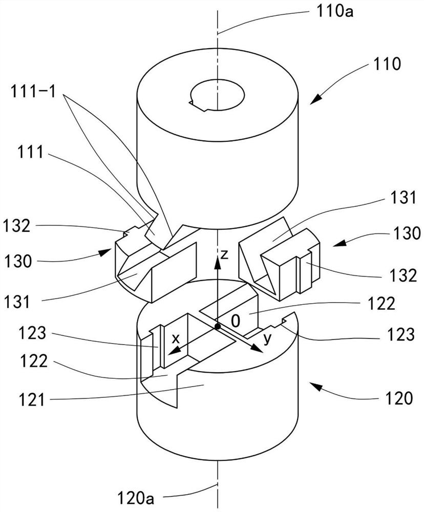
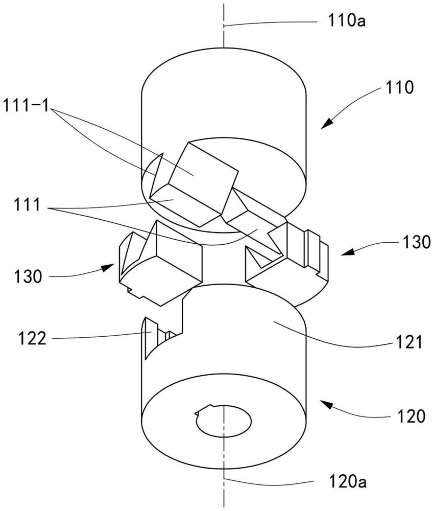
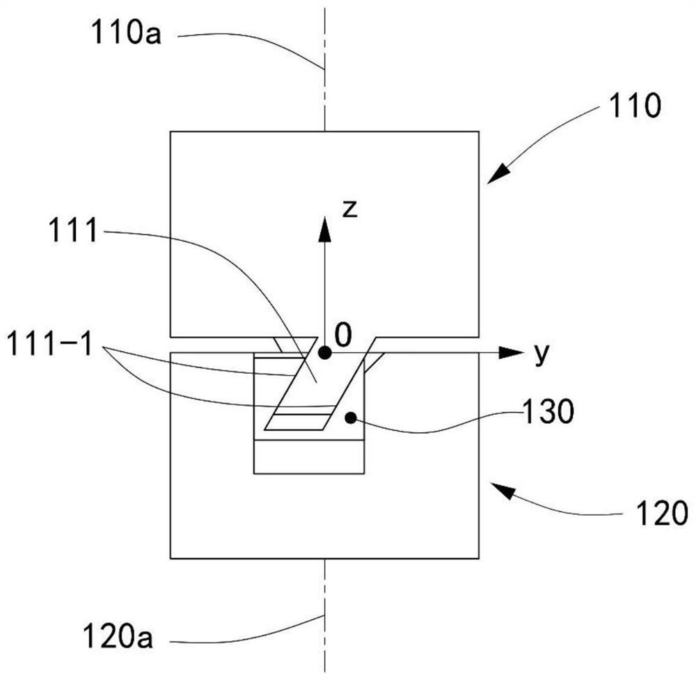
[0023] Such as figure 1 with figure 2 Shown is the coupling provided by the first embodiment of the present invention, including a first half coupling 110 , a second half coupling 120 and an intermediate connecting member 130 connecting the two half couplings 110 and 120 . The intermediate connecting piece 130 can only be slidably connected to the second half-coupling 120 in the axial direction, that is, it can only be slidably connected to the second half-coupling in the axial direction but not relatively rotatable. device 120. At the same time, the intermediate connecting piece 130 connects the second coupling 120 to the first coupling half 110 so that it can move freely in all directions along an inclined plane on the first coupling half 110. plane, and in the following description, unless otherwise specified, "inclined" is interpreted as inclined to a radial plane.

[0024] Here, the rotation axis of the first half-coupling 110 is referred to as the first rotation axis...


PUM


Abstract

The invention discloses a coupling comprising a first half coupling body, a second half coupling body and middle connecting pieces. One end of the first half coupling body is provided with at least one pair of protruding teeth, two pairs of sliding contact faces are arranged on the two protruding teeth belonging to the same pair respectively, the inclination directions of the sliding contact faces are opposite, and the included angles between the sliding contact faces and the radial plane are equal. The second half coupling body is provided with an end section which is staggered with the protruding teeth. The middle connecting pieces are connected to the end section in a sliding mode and can only move freely in the axial direction, inclined sliding grooves are formed to be matched with the protruding teeth, and the second half coupling body can be connected to the protruding teeth in a mode that the second half coupling body can move freely in all directions of the sliding contact faces. Meanwhile, each protruding tooth is at least matched with one middle connecting piece, the mass of the middle connecting pieces matched with the two protruding teeth belonging to the same pair is equal, and the common mass center of all the middle connecting pieces matched with the protruding teeth in the pair is arranged on a rotating shaft of the second half coupling body. Therefore, radial deviation and axial deviation between the two shafts can be compensated, and dynamic loads generated by the middle connecting pieces can be mutually counteracted inside to achieve balance.

Description

technical field [0001] The invention relates to the field of mechanical transmission, in particular to a coupling capable of compensating radial and axial offsets between two transmission shafts. Background technique [0002] In the field of mechanical transmission, a coupling is often used to connect the driving shaft and the driven shaft to transmit the rotational motion from the driving shaft to the driven shaft. Due to the influence of manufacturing, assembly and other factors, the driving shaft and the driven shaft are not completely Coaxial, there is always a radial, axial or angular relative offset between the two axes. In order to ensure stable transmission between the two shafts, the coupling needs to have a certain offset compensation capability. [0003] The Oldham coupling, also known as the Oldham coupling, is a coupling commonly used to compensate for the radial offset between two transmission shafts. Sliding to achieve the effect of compensating the radial o...

Claims


Application Information

Patent Timeline
Patent Type & Authority Applications(China)
IPC IPC(8): F16D3/04F16D3/06
CPCF16D3/04F16D3/06
Inventor 李隆昌
Owner 李隆昌
Learn More