
Liquid crystal display device

一种液晶显示、器件的技术,应用在液晶显示器件领域,能够解决消光区和消光量增大、亮度降低、不进行最佳化等问题

Inactive Publication Date: 2004-04-14
SHARP KK
View PDF3 Cites 2 Cited by
  • Summary
  • Abstract
  • Description
  • Claims
  • Application Information

AI Technical Summary

Problems solved by technology

[0007] However, in the above-mentioned conventional example, for example, as shown in the first paragraph of Example 7 in US Patent No. 6,384,889 (corresponding to paragraph [0039] in the above-mentioned Japanese Patent Application Laid-Open No. 2000-47251), adding a chiral agent , so that the chiral agent pitch is 18 [μm], which is roughly 4 times the cell thickness, and the twist angle at the time of voltage application is set to 90 degrees, but in this condition, the extinction pattern remains remarkably, and the extinction pattern of the extinction pattern area and the amount of extinction increases, and as a result, there are problems such as a decrease in transmission intensity occurs, resulting in a decrease in brightness
[0008] In addition, in the liquid crystal display device disclosed in U.S. Publication No. 0036740 (publication date: March 28, 2002), although it includes a structure in which the liquid crystal becomes a twisted structure in order to stabilize the orientation of the liquid crystal, the extinction is eliminated. pattern, or, there is no concept of increased transmittance by doing so
In addition, the optimization for the above cases is not performed

Method used


Image

  • Liquid crystal display device
  • Liquid crystal display device
  • Liquid crystal display device

Examples


Embodiment Construction

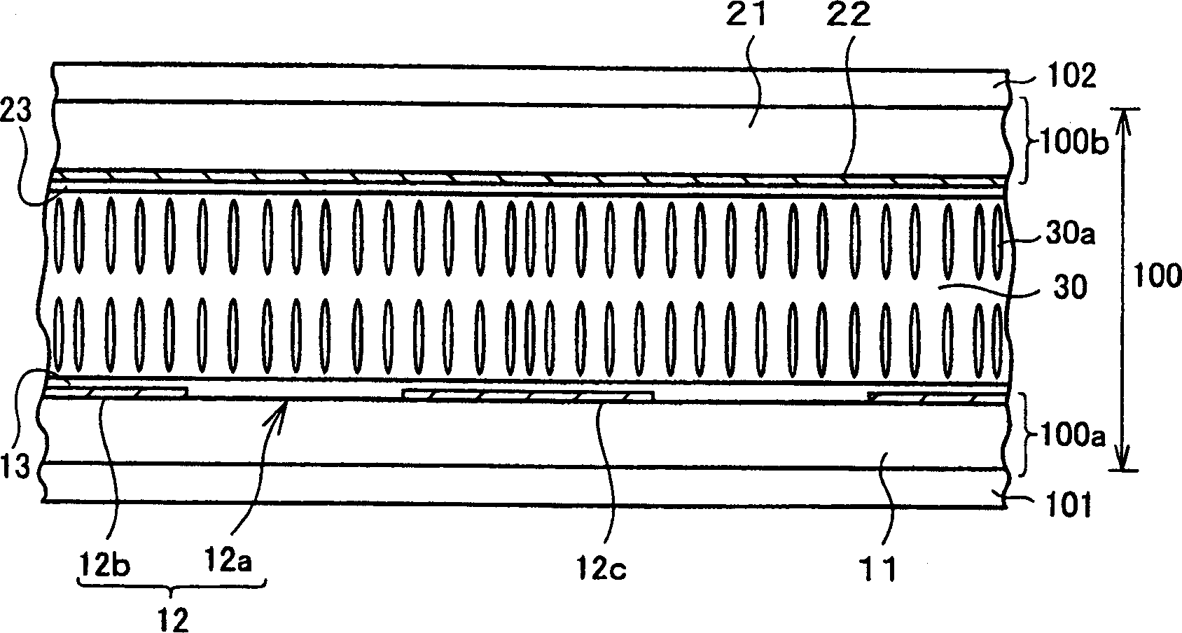
[0065] Now according to Figure 1 to Figure 50 An example illustrating the present invention is as follows. That is, although the liquid crystal display device of this embodiment has a high area transmission intensity, it does not produce a extinction pattern, and is a liquid crystal display device capable of displaying good quality, such as figure 2 As shown, it includes a liquid crystal cell 100 in a vertical alignment mode and polarizers 101 and 102 disposed on both sides of the liquid crystal cell 100 .

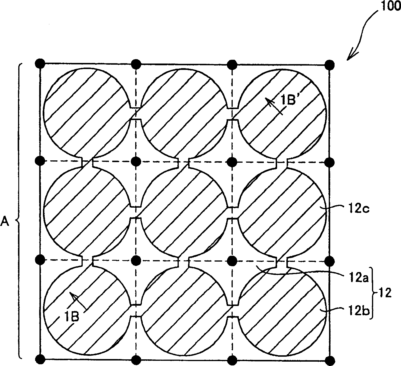
[0066] The liquid crystal cell 100 has an active matrix substrate (hereinafter referred to as "thin film transistor (TFT) substrate") 100a such as a thin film transistor (TFT) substrate, and an opposing substrate such as a color filter substrate (hereinafter also referred to as "color filter substrate"). Substrate") 100b and the liquid crystal layer 30 provided between the TFT substrate 100a and the opposite substrate 100b. In addition, the above-mentioned TFT substrat...


PUM


Abstract

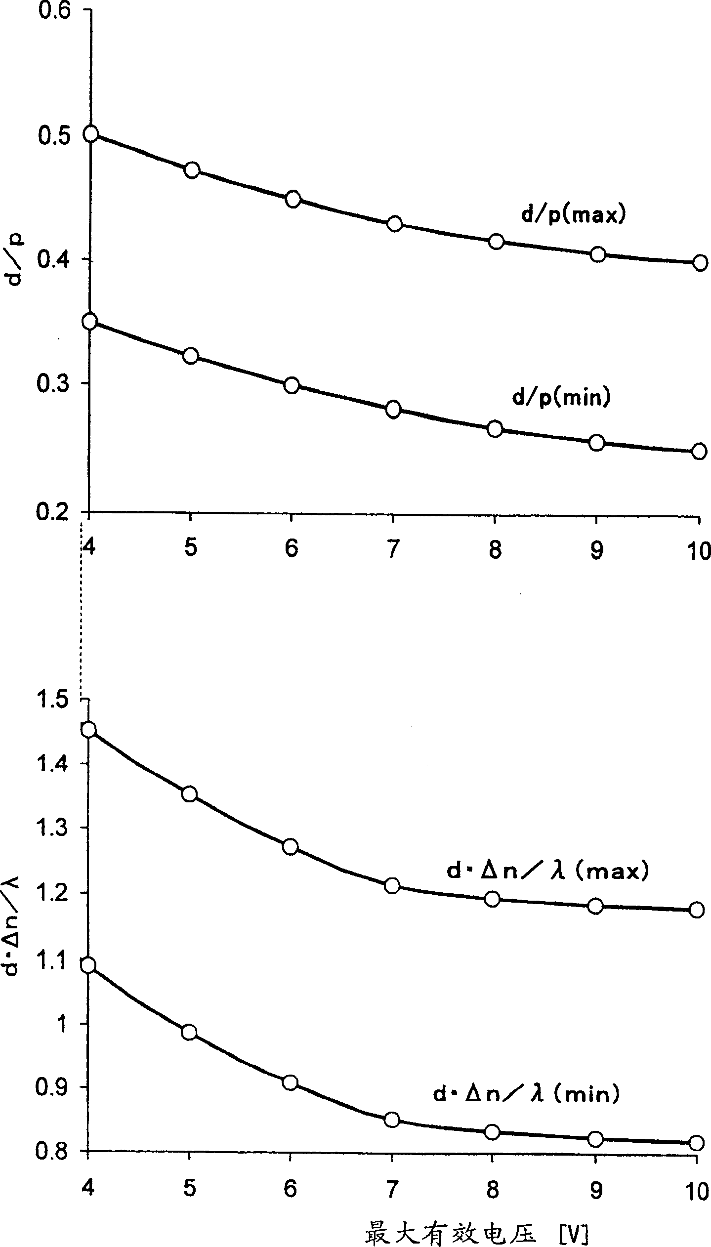
A liquid crystal display device of a vertical alignment mode is provided in which a quenching pattern, which is generated by such liquid crystal molecules whose in-plane component of the alignment directions under applied voltage is aligned along the cross nicole directions, is unrecognizable for a user. In the liquid crystal display device of a vertical alignment mode, a liquid crystal layer is has a defined value of d / p between 0.0021x(Vmax)2-0.0458x(Vmax)+0.65 and 0.0021x(Vmax)2-0.0458x(Vmax)+0.50, and a defined value of d.Deltan / lambda between -0.00026x(Vmax)3+0.016x(Vmax)2-0.2281x(Vmax)+2.124 and -0.00026x(Vmax)3+0.016x(Vmax)2-0.2281x(Vmax)+1.7603, where Vmax [V] is the maximum applied effective voltage applied to the liquid crystal layer.

Description

technical field [0001] The present invention relates to a liquid crystal display device in a vertical alignment mode. Background technique [0002] Conventionally, liquid crystal display devices have been widely used as screens of word processors and computers, and in recent years have also rapidly become popular as screens of televisions. Many of these liquid crystal display devices employ a TN (twisted nematic) mode, but such liquid crystal display devices tend to lower the contrast and tend to reverse the gradation characteristics when viewed obliquely. [0003] Therefore, in recent years, in order to improve the viewing angle characteristics viewed from an oblique direction, for example, those corresponding to Japanese Unexamined Patent Publication No. 2000-47251 (publication date: February 18, 2000, hereinafter referred to as a conventional example) of Japanese Laid-Open Gazette Liquid crystal display devices of VA (Vertical Alignment) mode, such as the liquid crystal ...

Claims


Application Information

Patent Timeline
Patent Type & Authority Applications(China)
IPC IPC(8): G02F1/1333G02F1/1337G02F1/1343G02F1/139
CPCG02F1/133707G02F1/134336G02F1/1393G02F1/1337
Inventor 荻岛清志久保真澄
Owner SHARP KK
Learn More