A self-anchored pipeline interface structure

A pipeline interface and self-anchoring technology, which is applied in the direction of pipes/pipe joints/fittings, engine seals, passing components, etc., can solve problems such as inability to rotate, poor installation of steel balls, and obstacles to smooth sliding of steel balls, etc., to achieve roundness The bead sliding channel is smooth, avoiding local narrow conditions, and reducing the difficulty of construction operations

Active Publication Date: 2022-08-05
SHANDONG GUOMING DUCTILE IRON PIPES TECH CO LTD
View PDF1 Cites 1 Cited by
  • Summary
  • Abstract
  • Description
  • Claims
  • Application Information

AI Technical Summary

Problems solved by technology

[0004] Although the ball self-locking pipe interface structure is more convenient to operate than the traditional locking structure, it can also meet the needs of anti-loosening under tension conditions to a large extent, but it is still found to affect the construction efficiency during verification and construction. Factors, such as the aforementioned "cast pipe self-anchor interface" structure, the steel ball 1-4 is loaded through the steel ball inlet 1-7 located at the top of the cast pipe socket 1-1, and falls by gravity. If there is an installation problem during construction When the two cast pipes need to be unlocked, the assembled cast pipe needs to be rotated so that the steel ball inlet is at the bottom to take out the steel ball. At this time, the cast pipe is usually unable to rotate or even if it is allowed to rotate, it is very difficult to operate, and the workers This is also the case when you choose the wrong steel ball specification during operation and need to take it out and reinstall it.
[0005] Another problem faced in the construction is the problem of poor installation of steel balls 1-4 and the problem of concentrated force at the joint end of the cast pipe under high tension. When loading steel balls, if the two cast pipes are axially horizontal or radially parallel The degree has not been adjusted properly, and the steel ball sliding passage on the butt joint surface may be partially narrow. At this time, since the stop ring 1-3 is welded to the outer wall of the socket, there is accumulated welding material at the corner of the steel ball sliding passage. Once the welding material If the local accumulation is too high, it will directly hinder the smooth sliding of the steel ball, and the accumulated welding material on the other side of the stop ring 1-3 may hinder the end of the stop ring when the cast pipe socket 1-5 is just inserted into the cast pipe socket 1-1. The upper part cannot be close to the vertical wall of the steel ball groove 1-6, which will also cause the steel ball to slide down the channel to narrow
In addition, the single-point conflict between the steel ball 1-4 and the stop ring 1-3 may not only be the cause of the unsmooth sliding passage of the steel ball, but also the cause of the concentration of force at the interface of the cast pipe. The concentration of force at the interface of the cast pipe may cause Because the cast pipe socket 1-1 receives too much outward extrusion force from the steel ball, and the cast pipe socket 1-5 receives too much inward extrusion force from the steel ball, the sealing ring 1-2 is reduced. sealing effect

Method used


Image

  • A self-anchored pipeline interface structure
  • A self-anchored pipeline interface structure
  • A self-anchored pipeline interface structure

Examples


Embodiment 1

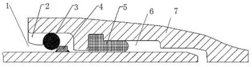
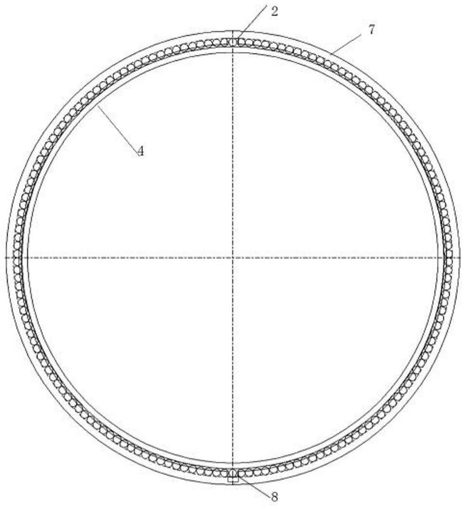
[0040] like figure 1 , figure 2 , image 3As shown, a self-anchored pipe interface structure in this embodiment includes a pipe body 7, one end of the pipe body 7 is a socket end 1, and the socket end 1 structure is reserved in the cast pipe body 7, The socket end 1 is matched with the socket end of the connecting pipe, and the socket end of the connecting pipe is inserted into the socket end 1. From the end face of the socket end 1, a ball installation port 2, a ball groove, Positioning groove 6, the ball 3 is installed in the ball groove, and the outer wall surface of the socket end of the connecting pipe is provided with a rigid ring 4, and the rigid ring 4 selects a material suitable for welding according to the material of the pipe, preferably iron or steel, The ball 3 is located in the cavity between the outer groove wall of the ball groove and the left side of the rigid ring 4 and can abut with the left corner of the rigid ring 4. The positioning groove 6 is located...

Embodiment 2

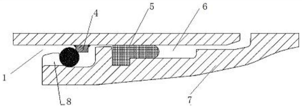
[0044] like Figure 4 , Figure 5 As shown, this embodiment is a further improvement to Embodiment 1, by Figure 4 , Figure 5 It can be seen that in this embodiment, the same as in Embodiment 1, the rigid ring 4 is also fixedly connected to the outer wall surface of the socket end of the connecting pipe by welding. The difference is that the part to be welded on the left side of the rigid ring 4 There is a chamfer 41 capable of accommodating solder.

[0045] In this embodiment, through the setting of the chamfer 41, at least a part of the solder can be accommodated, which prevents the local accumulation of the solder in the ball cavity from being too high, thereby largely avoiding the local narrowing that may occur in the ball sliding channel. Make the ball slide channel unobstructed.

Embodiment 3

[0047] like Image 6 , Figure 7 As shown, this embodiment is a further improvement on the basis of Embodiment 2, by Image 6 , Figure 7 It can be seen that, in this embodiment, in addition to the chamfer 41 that can accommodate at least a part of the solder on the left side of the rigid ring 4 to be welded, there is also a chamfer 41 that can accommodate at least a part of the weld on the right side of the rigid ring 4 Solder chamfer 41.

[0048] In this embodiment, by setting the chamfers 41 on the left and right sides, the solder on both sides can be respectively accommodated, which not only prevents the local solder accumulation in the ball cavity from being too high, but also prevents the rigid ring when the pipe socket is just inserted into the pipe socket. 4. The situation where the right side cannot be close to the vertical wall of the ball groove, thus avoiding the possible local narrowness of the ball sliding channel to the greatest extent, and making the ball sl...


PUM


Abstract

A self-anchored pipeline interface structure includes a pipeline body, one end of the pipeline body is a socket end, the socket end of the connected pipeline is inserted into the socket end, and a ball installation port and a ball ball are arranged in sequence from the end face of the socket end. Groove, positioning groove, balls are installed in the ball groove, a rigid ring is arranged on the outer wall of the socket end of the connecting pipe, the ball is located in the cavity between the outer groove wall of the ball groove and the left side of the rigid ring and can be connected with the rigid ring The left corner of the ring is abutted, the positioning groove is located on the right side of the rigid ring, a sealing rubber ring is arranged inside, and the lower side of the end of the socket end opposite to the ball installation port is provided with a corresponding disassembly port, and the ball can pass through the disassembly port After unloading, the rigid ring is welded on the outer wall of the socket end of the connecting pipe. The part to be welded is preferably provided with a chamfer or a welding groove capable of accommodating solder, and preferably a force component groove is formed at the left corner of the rigid ring. The invention further simplifies the operation, unblocks the ball sliding channel, reduces the stress concentration after assembly, and comprehensively improves the construction efficiency and the self-locking and anti-separation sealing effect.

Description

technical field [0001] The invention relates to the technical field of pipeline interface equipment, in particular to a self-anchored pipeline interface structure, which can be applied to the interface connection of cast pipe pipelines. Background technique [0002] The long-distance water transmission pipelines used by hydraulic, electric power, municipal and other engineering undertakings often need to overcome various complex ground conditions in application. When the connection port needs to bear a large tensile force, there are certain requirements for the connection method of the pipe interface. At present The most commonly used connection method on the market is the connection method in which the sealing ring is tightly squeezed between the socket and the socket. This method is easy to disengage due to less tensile force, while the external self-anchored interface structure connected by flanges The installation is complicated, there is a certain degree of difficulty i...

Claims


Application Information

Patent Timeline
Patent Type & Authority Patents(China)
IPC IPC(8): F16L25/10F16J15/10
CPCF16L25/10F16J15/104F16L37/23
Inventor 张学来王浩刘长森杨传花陈同玉李超刚
Owner SHANDONG GUOMING DUCTILE IRON PIPES TECH CO LTD
Why Eureka
Try Eureka