Function testing device for electronic product
An electronic product and functional testing technology, which is applied in the direction of measuring devices, measuring device casings, and components of electrical measuring instruments, etc., can solve the problems of reducing the working efficiency of electronic products and the inability to automatically draw evaluations of electronic products, etc.
- Summary
- Abstract
- Description
- Claims
- Application Information
AI Technical Summary
Problems solved by technology
Method used
Image
Examples
Embodiment 1
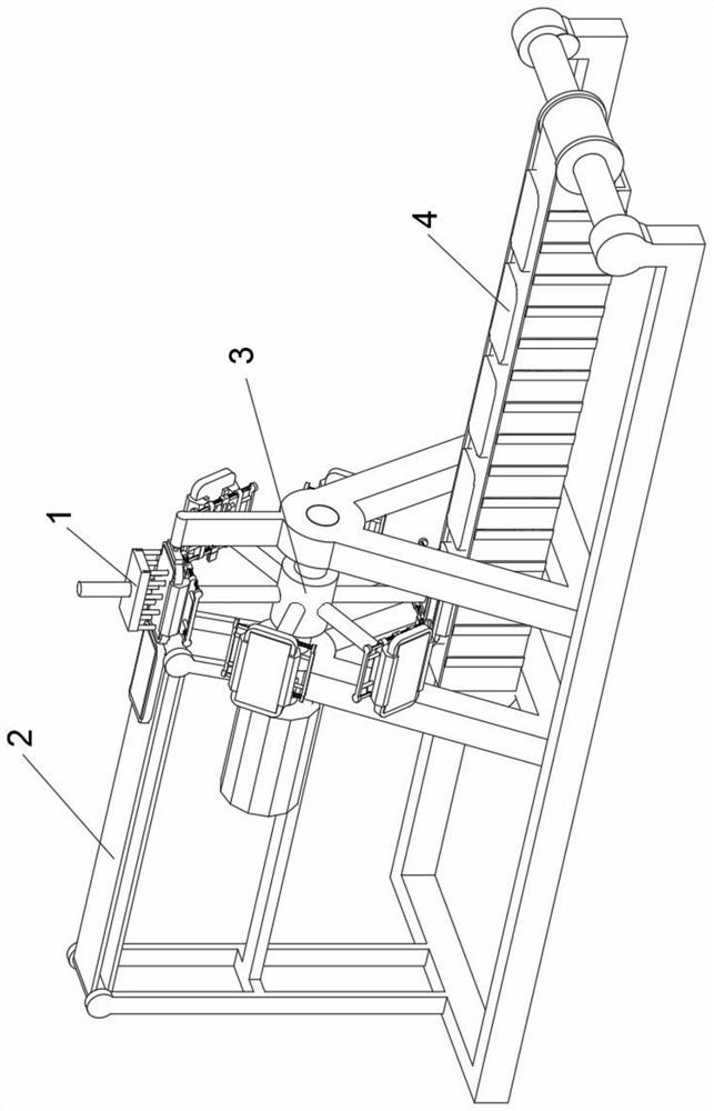
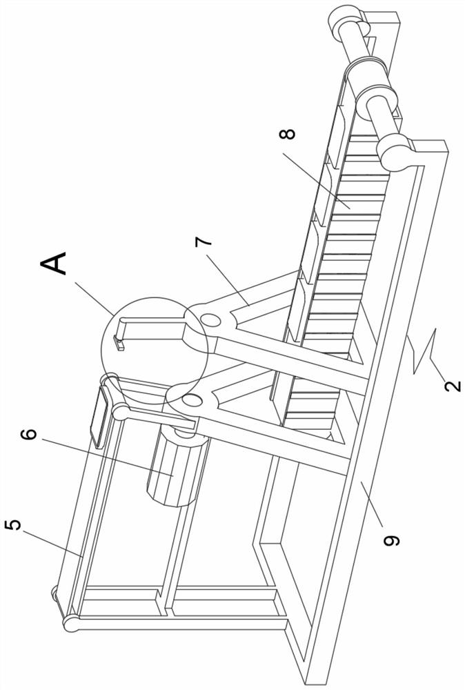
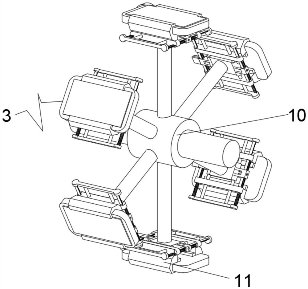
[0041] see Figure 1-2 , an embodiment provided by the present invention: a functional testing device for electronic products, including a tester 1, a support frame 2, a support frame 3 and an electronic product 4, the tester 1 is in conflict with the top of the support frame 3, The support frame 3 is rotatably installed in the middle of the support frame 2, the electronic product 4 is placed on the upper surface of one end center of the support frame 2, the inner bottom of the support frame 2 is fixedly installed with a fixed base 9, and the top center of the fixed base 9 is symmetrically fixed with a Triangular bracket 7, the top of one end of the support frame 2 is rotatably equipped with a feeding conveyor belt 5, the other end of the support frame 2 is rotatably equipped with a feeding conveyor belt 8, and the upper part of one end of the support frame 2 is fixed below the discharge conveyor belt 5 A driving motor 6 is installed;
[0042] see image 3 , the inside of th...
Embodiment 2
[0060] On the basis of Example 1, such as Figure 10 As shown, one end surface of the tooth plate 19 is fixedly connected to the limit clip 36, the inner surface of the clip groove 22 is evenly and fixedly connected with a rubber strip 37, and the top side of the second clip 17 is fixedly connected with a triangular clip 38 .
[0061] During the implementation of this embodiment, when the tooth plate 19 slides laterally, the groove 26 at one end will engage with the side surfaces of the first engaging block 16 and the second engaging block 17, so that the first engaging block 16 The position between the first engaging block 16 and the second engaging block 17 is limited to prevent the first engaging block 16 and the second engaging block 17 from sliding and separating from each other. When the two sides of 4 are snapped together, the rubber strip 37 on the inner surface of the snap slot 22 will protect the electronic product 4, thereby preventing the electronic product 4 from...
PUM
 Abstract
Description
Claims
Application Information
 - R&D
- Intellectual Property
- Life Sciences
- Materials
- Tech Scout
- Unparalleled Data Quality
- Higher Quality Content
- 60% Fewer Hallucinations
Browse by: Latest US Patents, China's latest patents, Technical Efficacy Thesaurus, Application Domain, Technology Topic, Popular Technical Reports.
© 2025 PatSnap. All rights reserved.Legal|Privacy policy|Modern Slavery Act Transparency Statement|Sitemap|About US| Contact US: help@patsnap.com


