
Thermomagnetic definite time limit structure and control and protection switching device

A fixed-time, thermal-magnetic technology, applied in the direction of magnetic/electric field switches, electric switches, circuits, etc., can solve the problems of affecting control and protection of switching appliances, failure to cut off the main circuit in time, and load damage, etc., to optimize key technical parameters, Reliable protection, not easy to damage the effect

Pending Publication Date: 2021-05-14
浙江中凯科技股份有限公司
View PDF0 Cites 0 Cited by
  • Summary
  • Abstract
  • Description
  • Claims
  • Application Information

AI Technical Summary

Problems solved by technology

[0005] Therefore, the technical problem to be solved by the present invention is to overcome the fact that the armature and the armature cover tend to be separated by a certain distance (the opening angles are different) in the prior art when the rotation center is rotated for many times. The series of actions will affect the smooth tripping of the control and protection switching appliances, and the main circuit cannot be cut off in time, resulting in damage to the load, thus providing a thermal magnetic definite time structure

Method used


Image

  • Thermomagnetic definite time limit structure and control and protection switching device
  • Thermomagnetic definite time limit structure and control and protection switching device
  • Thermomagnetic definite time limit structure and control and protection switching device

Examples


Embodiment 1

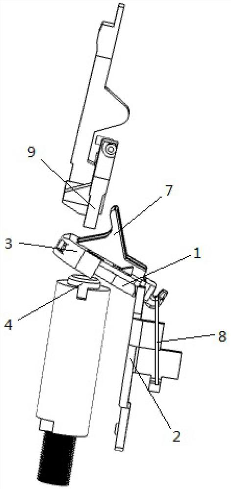
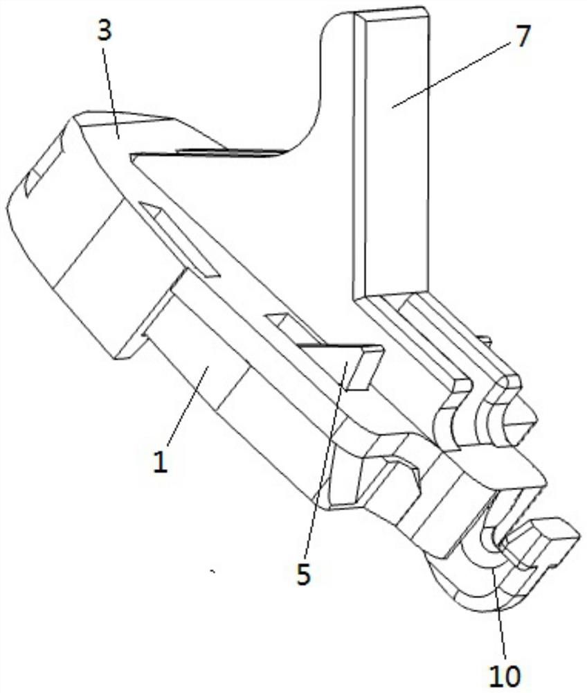
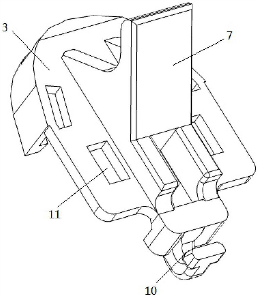
[0035] A thermal-magnetic definite time structure provided in this embodiment includes: an armature 1, an armature cover 3 and an iron core 4; the output part 7 and the hooking part 10 are both arranged on the armature cover 3, and all the forces received are concentrated on the armature On the cover 3, even after the armature 1 and the armature cover 3 rotate along the rotation center for many times, the armature 1 and the armature cover 3 tend to fit together, and there is no longer an opening angle, which ensures that the output part 7 of the armature cover 3 smoothly drives the control and The protection switching device trips smoothly, cuts off the main circuit, and realizes reliable protection for the load.

[0036] like figure 1 As shown, the armature 1 is rotatably arranged on the support plate 2. Specifically, the upper end of the support plate 2 has a U-shaped opening, and the two ends of the U-shaped opening are rotatably connected to the two ends of the armature 1;...

Embodiment 2

[0046] The control and protection switching device provided in this embodiment includes the thermomagnetism definite time structure described in Embodiment 1; the control and protection switching device may be a circuit breaker or other electrical appliances.


PUM


Abstract

The invention provides a thermomagnetic definite time limit structure and a control and protection switching electric appliance, and belongs to the technical field of low-voltage electric appliances. The thermomagnetic definite time limit structure comprises an armature which is rotatably arranged on a supporting plate, an armature cover connected with the armature, and an iron core, wherein the armature cover is provided with an extending output part and a hooking part for hooking the reaction spring; the reaction spring has a driving force for resetting the armature by pulling the armature cover; the iron core is arranged below the armature; and after a main circuit breaks down, the iron core has magnetic force used for attracting the armature to rotate. According to the thermomagnetic definite time limit structure, the output part and the hooking part are both arranged on the armature cover, and the borne force is concentrated on the armature cover, so that even if the armature and the armature cover rotate for multiple times along the rotation center, the armature and the armature cover tend to be attached, an opening angle is not formed any more, the output part of the armature cover is ensured to smoothly drive the control and protection switching device to trip smoothly, the main circuit is cut off, and reliable protection on a load is realized.

Description

technical field [0001] The invention relates to the technical field of low-voltage electrical appliances, in particular to a thermomagnetism definite-time structure and a control and protection switching appliance. Background technique [0002] The thermomagnetic module is an important component for controlling and protecting switching appliances. Its working principle is that when the motor starts, when the motor starts, the actual starting current of the main circuit exceeds a certain multiple of the set value within the set time, and its conductor The included iron core generates a large enough attraction force, which overcomes the reaction force of the reaction force spring and makes the armature quickly move toward the iron core along the rotation center, and the armature drives the armature cover, which in turn makes the push rod rotate and pushes the transmission mechanism to perform a series of movements. Action, and then trip the control and protection switch, cut o...

Claims


Application Information

Patent Timeline
IPC IPC(8): H01H36/00
CPCH01H36/00
Inventor 朱奇敏屠瑜权屠旭慰王小等翁金藏
Owner 浙江中凯科技股份有限公司
Learn More