Flywheel energy storage system, control method of flywheel energy storage system and storage medium

A flywheel energy storage and pre-charging technology, which is applied in the field of flywheel energy storage, can solve the problems that the electrochemical battery energy storage system cannot be fully charged, the economic efficiency is reduced, and the life of the electrochemical battery is impacted.

Active Publication Date: 2021-05-14
沈阳微控新能源技术有限公司
View PDF8 Cites 7 Cited by
  • Summary
  • Abstract
  • Description
  • Claims
  • Application Information

AI Technical Summary

Problems solved by technology

However, when the inertia of the power grid occurs, the required full-scale operation will greatly impact the life of the electrochemical battery. Therefore, operating in this environment will increase the frequency of battery replacement in new energy power stations and reduce economic efficiency.
Moreover, as the running time increases, it is difficult for the battery to be in a state of 100% effective capacity, and the effective capacity of the battery is one of the conditions that limit the stop of charge and discharge. When the battery voltage drops to a specified threshold, the discharge will stop. Therefore, the electrochemical The battery energy storage system cannot be fully charged

Method used


Image

  • Flywheel energy storage system, control method of flywheel energy storage system and storage medium
  • Flywheel energy storage system, control method of flywheel energy storage system and storage medium
  • Flywheel energy storage system, control method of flywheel energy storage system and storage medium

Examples


Embodiment Construction

[0028]Embodiments of the present invention will be described in detail below, and embodiments of the present invention will be described in detail below with reference to the embodiments described in detail below.

[0029]In order to solve the above problems, the first aspect of the invention proposes a flywheel energy storage system for assisting wind generator grid inertia, the flywheel energy storage system can achieve frequent depth charging and discharging, reducing the grid full load Risk and meet the economic adjustment method of smooth adjustment of wind turbines.

[0030]The flywheel energy storage system provided by the first aspect of the present invention is described below with reference to the accompanying drawings.

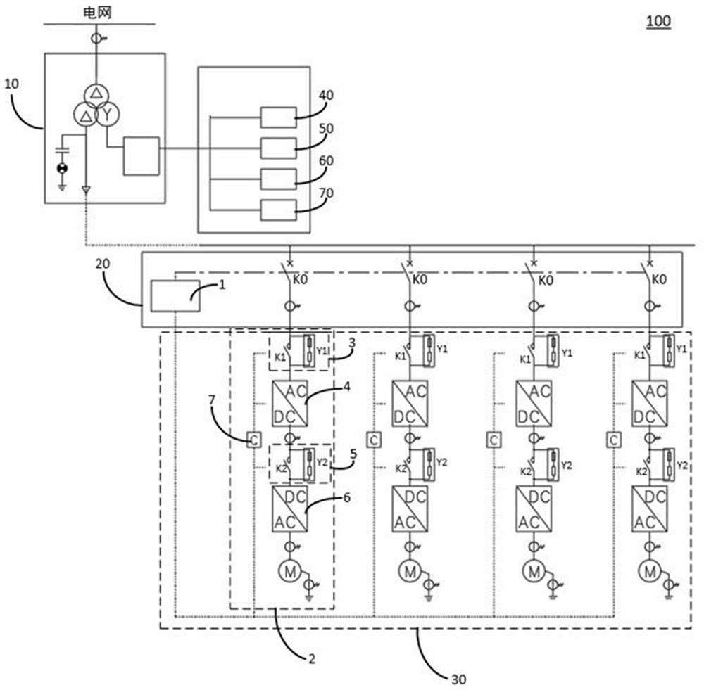
[0031]Such asfigure 1 As shown, the flywheel energy storage system 100 for assisting wind power grid inertia regulatory modulation includes a transformer 10, a total control device 20, and a magnetic suspension flywheel energy storage device 30.

[0032]Among them, t...


PUM


Abstract

The invention discloses a flywheel energy storage system, a control method of the flywheel energy storage system and a storage medium. The flywheel energy storage system used for assisting in power grid inertia adjustment of a wind driven generator comprises: a transformer; master control equipment, which comprises a master controller and N master control relays, wherein the first end of each master control relay is connected with the transformer, and the master controller is connected with each master control relay; a magnetic suspension flywheel energy storage device, which comprises N magnetic suspension flywheel energy storage branches arranged corresponding to the N master control relays. wherein each magnetic suspension flywheel energy storage branch comprises a first pre-charging loop, a first bidirectional converter, a second pre-charging loop, a second bidirectional converter, a motor and a flywheel controller. According to the flywheel energy storage system for assisting in power grid inertia adjustment of the wind driven generator, frequent and deep charging and discharging can be achieved, the risk of full-load power protection of the power grid is reduced, and the economic adjustment mode of smooth adjustment of the wind driven generator is met.

Description

Technical field[0001]The present invention relates to the field of flywheel energy storage, and more particularly to a flywheel energy storage system, a flywheel energy storage system for auxiliary wind power grid inertia, a computer storage medium.Background technique[0002]With the development of new energy and the development of grid technology, the ratio of new energy in the grid is getting higher and higher, and there is still a large number of microgrids in combination with regional characteristics. New energy, especially wind power, is huge by natural environment, and the fan is used as its power generation equipment, and it is necessary to assume the role of adjusting grid stability and continuous power generation.[0003]In the relevant technique, wind power new energy power plants use electrochemical battery energy storage systems as primary equipment. However, the complete depth movement of the demand during the moment of inertia occurs, the life of the electrochemical cell ...

Claims


Application Information

Patent Timeline
Patent Type & Authority Applications(China)
IPC IPC(8): H02J3/30H02J3/38
CPCH02J3/30H02J3/381H02J2300/28Y02E60/16Y02E70/30
Inventor 王聪李海超程祥
Owner 沈阳微控新能源技术有限公司
Why Eureka
Try Eureka