
A high-reflectivity powder coating spraying equipment for lamp production

A high-reflectivity, powder coating technology, used in coatings, devices that apply liquid to surfaces, etc., can solve problems such as uneven coating, low work efficiency, time-consuming and laborious, and achieve improved work efficiency and accurate rotation. Effect

Active Publication Date: 2021-11-19
济南汇金电器有限公司
View PDF0 Cites 0 Cited by
  • Summary
  • Abstract
  • Description
  • Claims
  • Application Information

AI Technical Summary

Problems solved by technology

[0005] In order to overcome the fact that when the work is done manually, uneven coating may occur, which will lead to low working efficiency. If there are many lamps to be sprayed, it will also cause time-consuming and labor-intensive shortcomings. The technical problem of the present invention is to provide an automatic Spraying lamps, high reflectivity powder coating spraying equipment for lamp production with good spraying effect and easy operation

Method used


Image

  • A high-reflectivity powder coating spraying equipment for lamp production
  • A high-reflectivity powder coating spraying equipment for lamp production
  • A high-reflectivity powder coating spraying equipment for lamp production

Examples


Embodiment 1

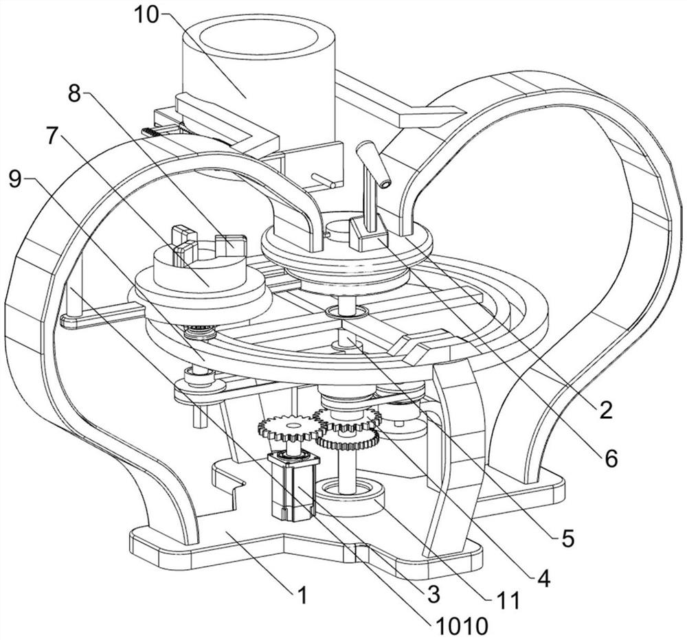
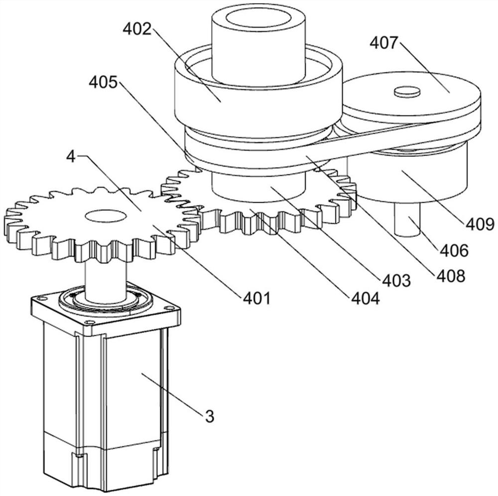
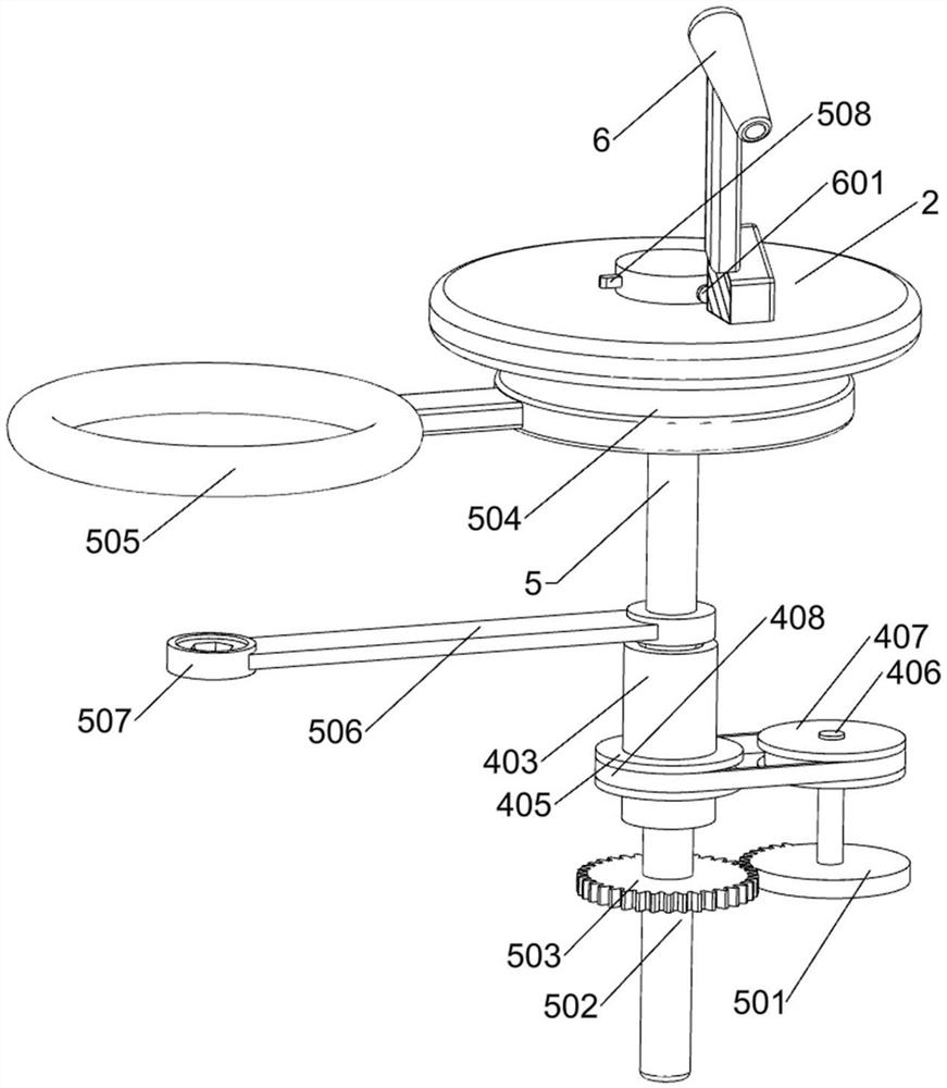
[0029] A high-reflectivity powder coating spraying equipment for lamp production, such as figure 1 , figure 2 , image 3 and Figure 4 As shown, it includes a base 1, a first support plate 2, a motor 3, a transmission assembly 4, an intermittent rotation assembly 5, a nozzle 6, a touch switch 601 and a shelf 7. The upper middle of the base 1 is provided with a first support plate 2, and the base 1. A motor 3 is provided on the left side of the upper middle part. A transmission assembly 4 is provided on the rear side of the upper middle part of the base 1. An intermittent rotation assembly 5 is provided between the first support plate 2 and the base 1. A nozzle is provided on the front side of the top of the first support plate 2. 6. A touch switch 601 is provided on the rear side of the lower part of the sprinkler head 6, and the touch switch 601 controls the sprinkler head 6, and the left side of the intermittent rotation assembly 5 is provided with a shelf 7.

[0030]The...

Embodiment 2

[0034] On the basis of Example 1, such as figure 1 , Figure 4 , Figure 5 , Figure 6 and Figure 7 As shown, a clamping assembly 8 is also included, and the clamping assembly 8 includes a second contact rod 801, a second support plate 802, a first spring 803, a first slider 804, a second slider 805 and a third contact rod 806, three first sliders 804 are provided with evenly spaced sliding inside the middle part of the storage rack 7, and the inner lower part of the first slider 804 is provided with a second contact rod 801, and the outer side of the upper part of the first slider 804 is provided with a second slider 805, three second support plates 802 are arranged on the inner side of the lower part of the storage rack 7 evenly spaced slidingly, and the first spring 803 is connected between the second support plate 802 and the first slider 804, and the third bearing 507 is provided with a rotating type. The third contact rod 806 , the third contact rod 806 can slide up...


PUM


Abstract

The invention relates to a spraying equipment, in particular to a high-reflectivity powder coating spraying equipment for lamp production. The technical problem of the present invention is to provide an automatic spraying lamp, a high-reflectivity powder coating spraying equipment for lamp production with good spraying effect and simple operation. The technical solution of the present invention is a high-reflectivity powder paint spraying equipment for lamp production, including: a base; a first support plate, the first support plate is provided in the upper middle of the base; a motor is provided on one side of the upper middle of the base; The transmission assembly is provided with a transmission assembly on one side of the upper middle part of the base. The beneficial effect is: under the action of the intermittent rotating component, people place the lamp on the shelf, start the motor, and after a series of transmissions, the third transmission rod will drive the first contact rod to rotate 90 degrees, and the first contact rod will rotate 90 degrees. When in contact with the touch switch, the nozzle will spray the paint onto the lamp, which effectively improves people's work efficiency.

Description

technical field [0001] The invention relates to a spraying equipment, in particular to a high-reflectivity powder coating spraying equipment for lamp production. Background technique [0002] Luminaires refer to appliances that can transmit light, distribute and change the light distribution of the light source, including all parts required to fix and protect the light source except the light source, as well as the necessary line accessories for connection to the power supply. [0003] In the process of lamp production, people will spray the surface of the lamp with high reflectivity powder. When people spray the surface of the lamp, they usually apply the paint evenly on the blockboard by hand, and then manually use a roller brush Apply the paint on the surface evenly. When this work is done manually, uneven application may occur, which will lead to low working efficiency. If there are many lamps to be sprayed, it will also be time-consuming and laborious. [0004] Therefo...

Claims


Application Information

Patent Timeline
Patent Type & Authority Patents(China)
IPC IPC(8): B05C19/04B05C13/02
CPCB05C13/02B05C19/04
Inventor 夏冬贵
Owner 济南汇金电器有限公司
Learn More