
Welding robot

A welding robot and robotic arm technology, applied in the field of robotics, can solve the problems of staff retinal burns, affecting welding accuracy, and inability to cycle welding, etc.

Inactive Publication Date: 2021-05-18
李紫霞
View PDF0 Cites 2 Cited by
  • Summary
  • Abstract
  • Description
  • Claims
  • Application Information

AI Technical Summary

Problems solved by technology

[0003] When using a welding robot, the workpiece is placed on the workbench, and the workpiece is welded by the welding robot. During the welding process, because the welding head of the robot is fixed, it is not convenient to perform multi-directional welding on the welded object, making the robot During the welding process, the position needs to be adjusted all the time, the welding head will shake due to the adjustment of the robot, which will affect the accuracy of welding, and the welding cannot be performed in a cycle, which greatly reduces the stability of product production, and the robot will produce strong and glare when welding. The arc light makes the staff prone to cataracts and retinal burns, which directly affects the health of the staff

Method used


Image

  • Welding robot
  • Welding robot
  • Welding robot

Examples


Embodiment 1

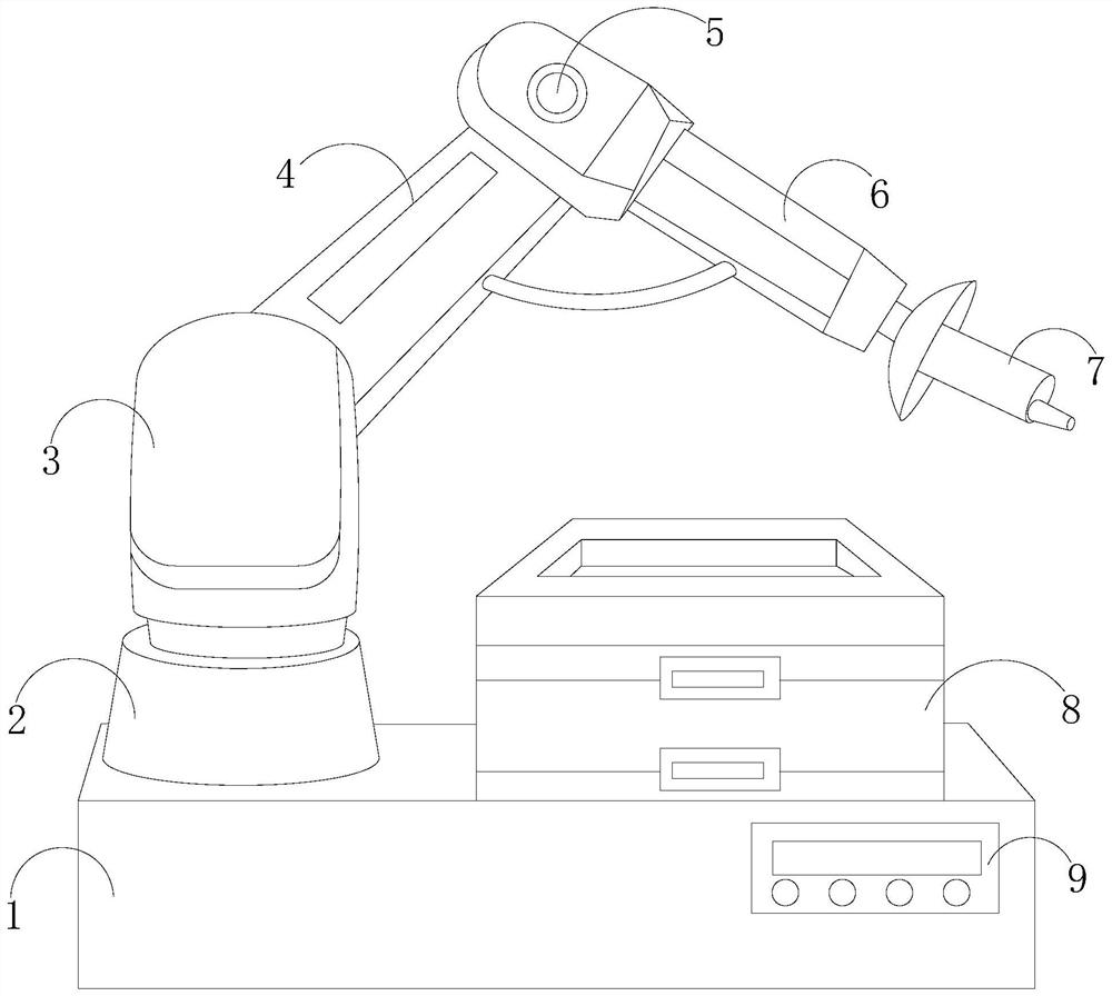
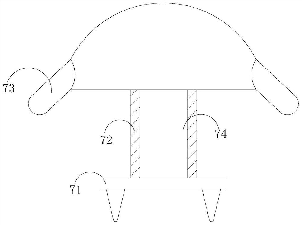
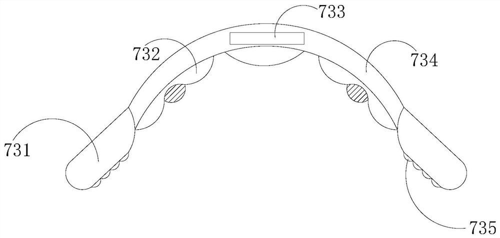
[0030] see figure 1 , the present invention provides a technical solution: a welding robot, the structure of which includes a main body 1, a positioning seat 2, a rotary table 3, a first mechanical arm 4, an adjustment shaft 5, a second mechanical arm 6, a movable device 7, and a workbench 8. Operation panel 9, the main body 1 and the operation panel 9 are connected by wires, the main body 1 is provided with a positioning seat 2 and a workbench 8 inlaid with it, and the positioning seat 2 and the workbench 8 pass through the main body 1 connected, the end of the positioning seat 2 away from the main body 1 is movably engaged with the turntable 3, the turntable 3 is buckled with the first mechanical arm 4, and the end of the first mechanical arm 4 far away from the turntable 3 is connected to the The adjustment shaft 5 is connected, the adjustment shaft 5 is fixedly connected with the second mechanical arm 6, the second mechanical arm 6 is connected with the first mechanical a...

Embodiment 2

[0041] see figure 1 , the present invention provides a technical solution: a welding robot, the structure of which includes a main body 1, a positioning seat 2, a rotary table 3, a first mechanical arm 4, an adjustment shaft 5, a second mechanical arm 6, a movable device 7, and a workbench 8. Operation panel 9, the main body 1 and the operation panel 9 are connected by wires, the main body 1 is provided with a positioning seat 2 and a workbench 8 inlaid with it, and the positioning seat 2 and the workbench 8 pass through the main body 1 connected, the end of the positioning seat 2 away from the main body 1 is movably engaged with the turntable 3, the turntable 3 is buckled with the first mechanical arm 4, and the end of the first mechanical arm 4 far away from the turntable 3 is connected to the The adjustment shaft 5 is connected, the adjustment shaft 5 is fixedly connected with the second mechanical arm 6, the second mechanical arm 6 is connected with the first mechanical a...


PUM


Abstract

The invention discloses a welding robot. The welding robot structurally comprises a main body, a positioning seat, a rotating table, a first mechanical arm, an adjusting shaft, a second mechanical arm, a movable device, a workbench and an operation panel. When the welding robot is used, a movable fixed block can rotate clockwise along with movement of a rotating disc, the direction and the position of a welding joint are adjusted in multiple directions, large friction resistance can be generated between an auxiliary sliding piece and a friction piece, so that the welding joint is not prone to swing and shift, and workpieces can be circularly welded; and then a protective layer and a blocking piece are matched with each other for double light filtering, so that arc light generated by welding cannot directly irradiate the eyes of workers, and damage of welding strong light to the eyes is avoided.

Description

technical field [0001] The invention relates to the field of robots, in particular to a welding robot. Background technique [0002] With the development of society and the progress of economy, welding robots that assist people in welding work have also emerged. Welding robots are industrial robots engaged in welding. Welding electrodes are installed on the execution end of industrial robots to enable them to perform welding operations. A device that adjusts the welding head through the adjustment element. When using a welding robot, the areas that need to be improved: [0003] When using a welding robot, the workpiece is placed on the workbench, and the workpiece is welded by the welding robot. During the welding process, since the welding head of the robot is fixed, it is not convenient to perform multi-directional welding on the welded object, making the robot During the welding process, the position needs to be adjusted all the time. The welding head will shake due to t...

Claims


Application Information

Patent Timeline
IPC IPC(8): B23K9/32B23K9/12
CPCB23K9/12B23K9/321
Inventor 王金法
Owner 李紫霞
Learn More