
Concrete brick forming groove for building construction

A technology for concrete bricks and building construction, which is applied to ceramic molding machines, manufacturing tools, molds, etc., and can solve the problems of air holes inside or outside the bricks, high manufacturing costs, uneven distribution, etc.

Inactive Publication Date: 2021-05-18
温州顺启建筑有限公司
View PDF16 Cites 0 Cited by
  • Summary
  • Abstract
  • Description
  • Claims
  • Application Information

AI Technical Summary

Problems solved by technology

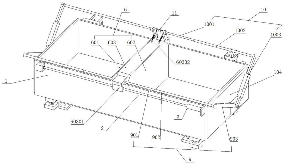
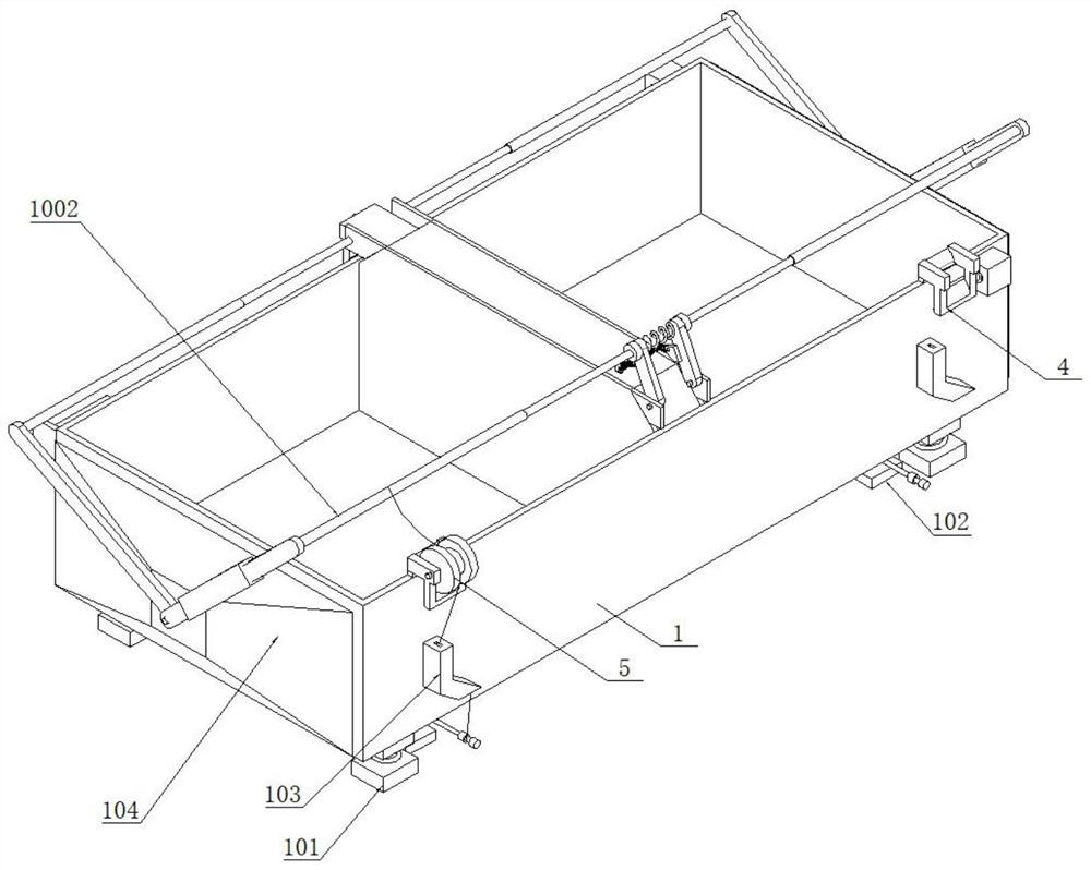
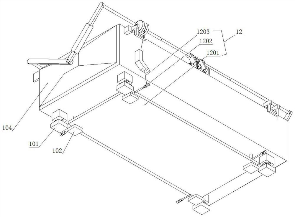
[0003] Most of the existing forming troughs are single-station structures, which can only form one piece at a time, and the work efficiency is low. In the same construction environment, it is necessary to prepare a variety of forming troughs. The forming groove lacks a vibrating mechanism, which makes the distribution of bricks uneven after forming, and air holes appear inside or outside the bricks, which affects the quality

Method used


Image

  • Concrete brick forming groove for building construction
  • Concrete brick forming groove for building construction
  • Concrete brick forming groove for building construction

Examples


Embodiment Construction

[0032] The following is a clear and complete description of the technical solution of the patent of the present invention in conjunction with the accompanying drawings. Apparently, the described embodiments are part of the embodiments of the present invention, not all of them. Based on the embodiments of the present invention, all other embodiments obtained by those skilled in the art without creative efforts fall within the protection scope of the present invention.

[0033] In the description of the present invention, it should be noted that if the terms "center", "upper", "lower", "left", "right", "vertical", "horizontal", "inner", "outer" appear The orientation or positional relationship indicated by etc. is based on the orientation or positional relationship shown in the drawings, and is only for the convenience of describing the present invention and simplifying the description, rather than indicating or implying that the referred device or element must have a specific or...


PUM


Abstract

The invention relates to a concrete brick forming groove for building construction. The concrete brick forming groove comprises a groove body and a vibration plate mechanism. A motor is installed on the right side of the front part of the groove body, a bearing seat is installed on the left side of the groove body, and a screw is installed between the motor and the bearing seat. A sliding rod is installed on the rear part of the groove body, a partition frame mechanism is located in the groove body, the front side of the partition frame mechanism is installed on the screw, the rear side of the partition frame mechanism is installed on the sliding rod, so that when the screw rotates, the partition frame mechanism is driven to move left and right in the groove body. When a vibration motor is electrified to vibrate, a left vibration plate and a right vibration plate generate a vibration effect, the vibration plate mechanism with a beating effect is further arranged at the bottom of the groove body, in the using process, an operator steps on a vibration rod on the rear side to enable the vibration plate mechanism to beat the bottom face of the groove body, and the purpose of vibration type material uniformizing of pug falling to the bottom of a groove cavity is achieved. Therefore, during actual use, the groove body has the multidirectional vibration characteristic of the inside, the side and the bottom, and the working efficiency and the forming quality of concrete materials during brick making forming are greatly improved.

Description

technical field [0001] The invention relates to the technical field of building construction, in particular to a concrete brick forming groove for building construction. Background technique [0002] During the building construction process, according to the construction needs, some construction bricks need to be made. In order to improve work efficiency and quality, they need to be formed quickly by using forming grooves. There are almost no concrete bricks on the market. The "concrete bricks" used on the construction site are all Self-made, the main purpose is to measure the openings of doors and windows, and the brick wall formed by stacking has higher strength and better quality. [0003] Most of the existing forming troughs are single-station structures, which can only form one piece at a time, and the work efficiency is low. In the same construction environment, it is necessary to prepare a variety of forming troughs. The forming groove lacks a vibrating mechanism, so...

Claims


Application Information

Patent Timeline
IPC IPC(8): B28B7/00B28B1/087
CPCB28B7/24B28B7/0029B28B7/0002B28B1/087
Inventor 李旺李玉辉
Owner 温州顺启建筑有限公司
Learn More