

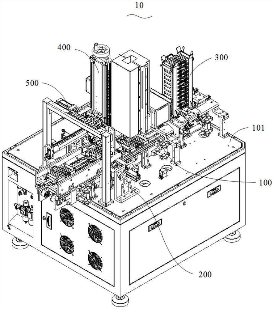
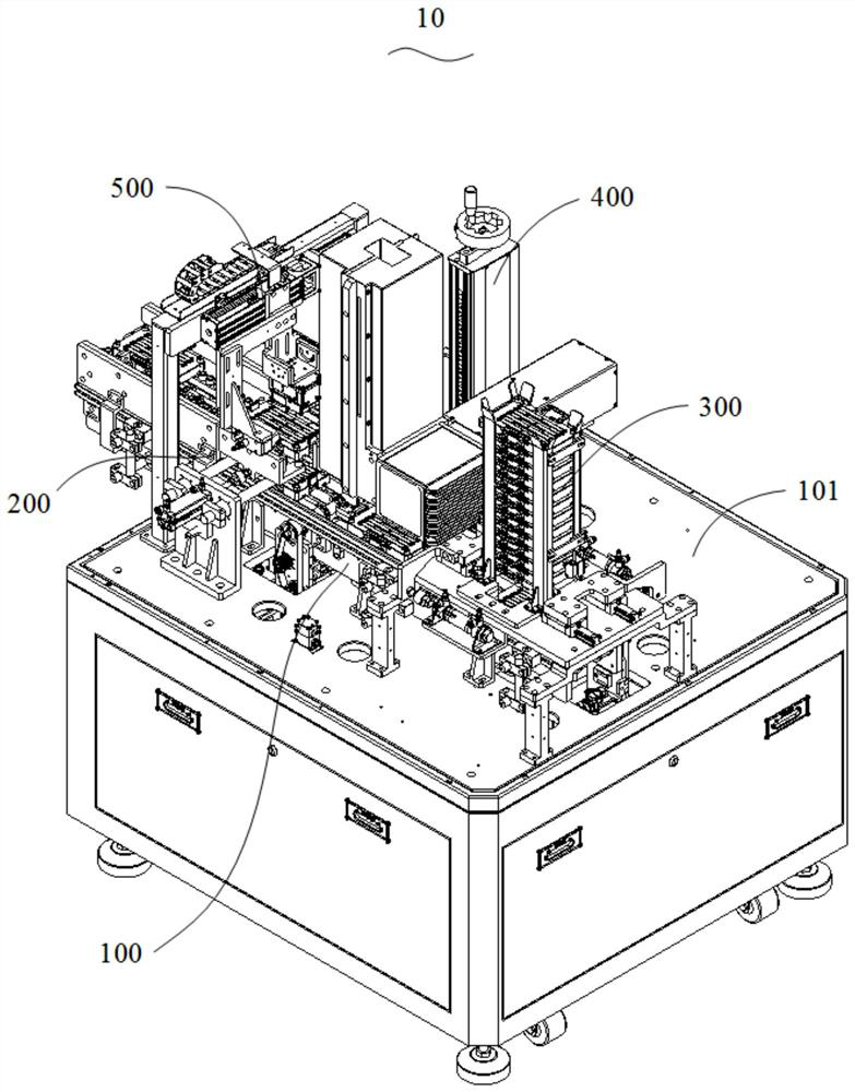
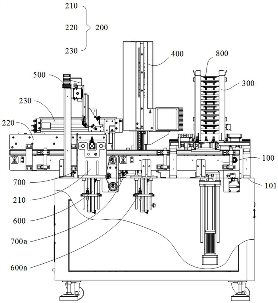
Laser marking equipment
A laser marking equipment, marking machine technology, applied in typewriters, printing, sorting and other directions, can solve the problems of wasting manpower, not realizing full automation, and low efficiency.
- Summary
- Abstract
- Description
- Claims
- Application Information
AI Technical Summary
Problems solved by technology
Method used
Image

Examples
Embodiment Construction
[0037] The following will clearly and completely describe the technical solutions in the embodiments of the present invention with reference to the accompanying drawings in the embodiments of the present invention. Obviously, the described embodiments are only part of the embodiments of the present invention, not all of them. Based on the embodiments of the present invention, all other embodiments obtained by persons of ordinary skill in the art without creative efforts fall within the protection scope of the present invention.
[0038] In the present invention, unless otherwise specified and limited, the terms "connection" and "fixation" should be understood in a broad sense, for example, "fixation" can be a fixed connection, a detachable connection, or an integral body; It can be a mechanical connection or an electrical connection; it can be a direct connection or an indirect connection through an intermediary, and it can be an internal communication between two elements or a...
PUM
 Abstract
Description
Claims
Application Information