a plaster head

A technology of components and forming panels, applied in the direction of construction and building construction, can solve the problems of high labor intensity, high labor cost, and difficult to stabilize quality, and achieve the effects of high degree of automation, small overall quality, and improved utilization rate

Active Publication Date: 2021-12-17
上海蔚建科技有限公司
View PDF0 Cites 0 Cited by
  • Summary
  • Abstract
  • Description
  • Claims
  • Application Information

AI Technical Summary

Problems solved by technology

Traditional manual plastering is labor-intensive, low-efficiency plastering, and requires high skill levels of workers. Therefore, plastering workers are a type of work that is relatively scarce in the construction industry, and labor shortages often occur.
And long-term plastering work in a high-temperature and high-pollution environment is prone to heatstroke, pneumoconiosis, strain and other occupational diseases
Generally speaking, the labor cost of traditional plastering is high, the efficiency is low, the quality is difficult to stabilize, and it is accompanied by safety and occupational disease risks
[0003] At present, most of the common plastering heads in the market are manually assisted, and a few of them can realize semi-automatic plastering, and in the actual operation process, more manual labor is still required to complete the plastering work together with the machine.
At the same time, each plastering operation of the existing plastering machine requires manual intervention in feeding, and after loading, it is necessary to spread the material manually so that the plastering operation can only be started after the mortar is evenly distributed over the entire plastering width. The process relies on manual experience, and the plastering quality is not easy to control
In addition, during the plastering process of the existing plastering machine, the plastering thickness is greater than the thickness that needs to be controlled in the actual plastering, and the thickness of the plastering is irregular, which leads to a large amount of mortar blanking in the subsequent scraping process
In addition, when the existing plastering machine is in the position of dusting and leveling, there is a large gap between the plastering board and the hopper, which will produce more blanking, superimposing the aforementioned scraping and blanking, both of which lead to the utilization rate of the mortar lower
Moreover, the existing plastering head needs more power sources to achieve different plastering actions, so there are too many components on the plastering head, which are easily polluted by mortar or seeped into sewage during cleaning, thereby damaging
In addition, the size of the existing plastering head is too large, and it is difficult to get in and out of the room when mounted on the plastering machine. More often, it needs to be dismantled to enter and exit the work room, which is time-consuming and laborious.
Finally, the cleaning of the existing plastering head is cumbersome, and it is troublesome to disassemble and assemble due to multiple fixed connections with other mechanisms, which is very inconvenient for cleaning and maintenance
Since the mortar has both solid and fluid properties, the mortar will inevitably enter the narrow and difficult-to-clean spaces such as the gaps and corners of the mechanism during the plastering process, but because the plastering head is fixedly connected with other mechanisms , it is difficult to disassemble and clean, and at the same time, it is close to the electrical components, and it is easy to splash water during cleaning, causing circuit and control failures. If it is dismantled and cleaned, the position accuracy after installation is easy to lose
[0004] In summary, the existing plastering heads have many problems such as manual intervention, poor plastering quality control, low mortar utilization rate, large size, and difficult cleaning and maintenance.

Method used


Image

  • a plaster head
  • a plaster head
  • a plaster head

Examples


Embodiment Construction

[0038] The present invention will be described in detail below in conjunction with specific embodiments. The following examples will help those skilled in the art to further understand the present invention, but do not limit the present invention in any form. It should be noted that those skilled in the art can make several modifications and improvements without departing from the concept of the present invention. These all belong to the protection scope of the present invention.

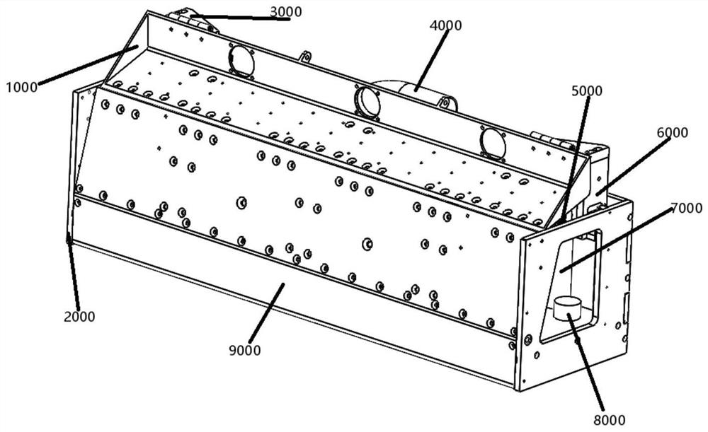
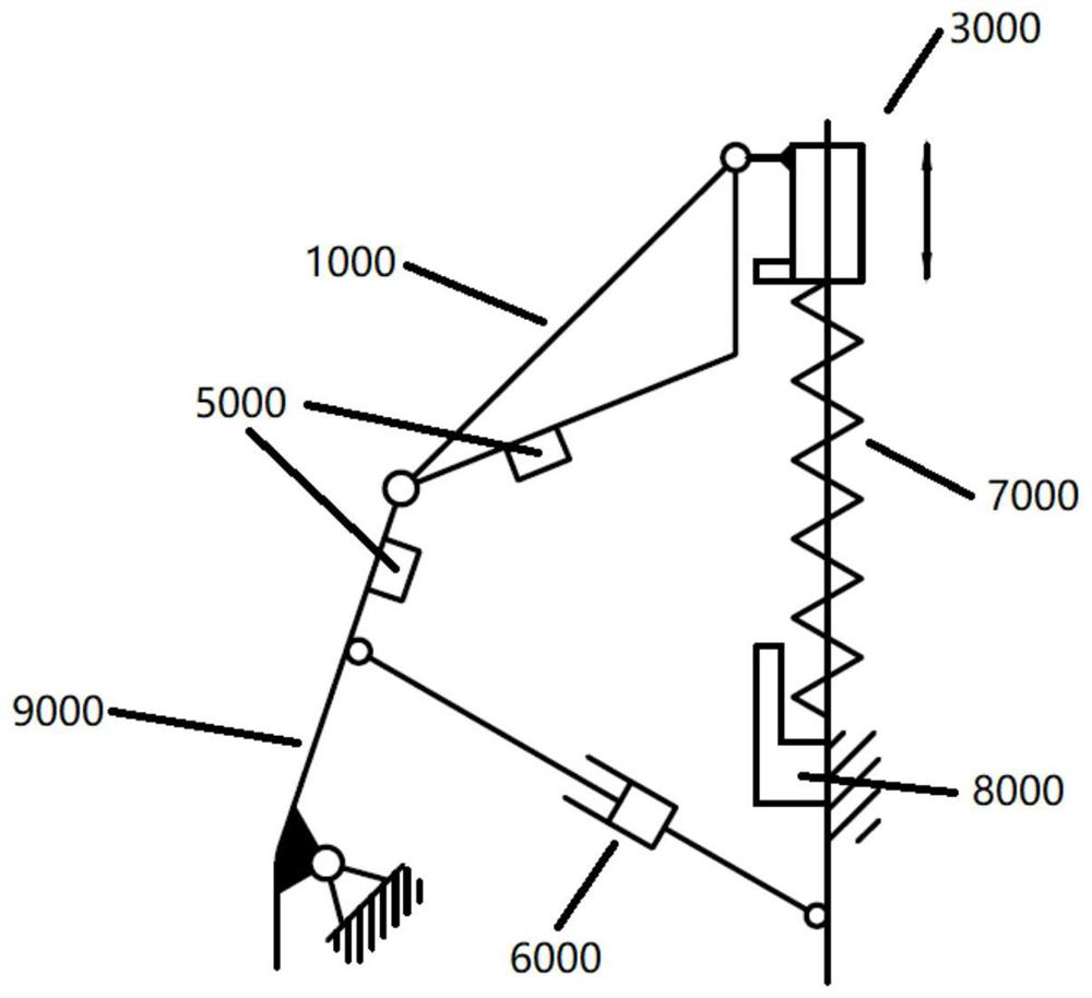
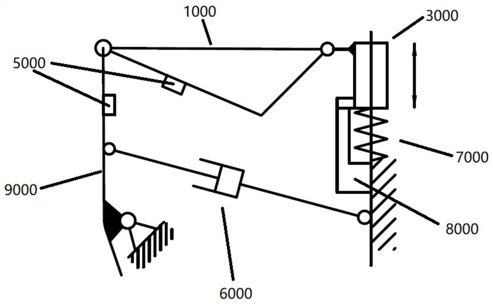
[0039] refer to figure 1 As shown, it is a structural schematic diagram of a plastering head in a preferred embodiment of the present invention. The plastering head is a kind of technical equipment mainly used for wall plastering, which can realize plastering, scraping, storage and storage of plastering media. Flattening operation, including frame 2000, forming plate 9000, hopper 1000 and linear moving parts 3000 in the figure;

[0040] Among them, the frame 2000 provides a fixed shell for the en...


PUM


Abstract

The invention provides a plastering head, which includes a frame, and a forming plate arranged on the frame for bonding the upper wall of the plastering medium; the forming plate is arranged at an acute angle to the vertical direction, and a wedge shape is formed between the forming plate and the wall surface space, the plastering head is in the posture of putting up the plaster; the hopper for flattening and storing the plastering medium is hinged with the upper end of the forming plate; the hopper is set on an inclined plane with the horizontal direction, so that the plastering medium flows into the wedge from the hopper under the action of gravity In the space; and the hopper can be turned downwards to drive the forming board to turn forward. When the forming board is turned upright, the plastering head changes from the dusting posture to the scraping posture; the linear moving parts limit the turning process The overturning action can be accurately realized, and when the linear moving part moves down to the specified position, its position can be kept fixed by the limiting part. The invention reduces manual intervention, has good plastering quality control, and has a high utilization rate of mortar; and realizes the processes of material supply, flattening, wall mounting, and scraping for plastering operations in a small space.

Description

technical field [0001] The invention relates to the technical field of plastering in building construction, in particular to a plastering head mainly used in the process of plastering walls. Background technique [0002] The plastering operation involves a lot of wet mortar work, and the construction specifications have high requirements on the quality of the plastering. Traditional manual plastering is labor-intensive, low-efficiency plastering, and requires high skill levels of workers. Therefore, plastering workers are a type of work that is relatively scarce in the construction industry, and there are often labor shortages. And long-term plastering work in a high-temperature and high-pollution environment is prone to heat stroke, pneumoconiosis, strain and other occupational diseases. Generally speaking, the labor cost of traditional plastering is high, the efficiency is low, the quality is difficult to stabilize, and it is accompanied by safety and occupational disease...

Claims


Application Information

Patent Timeline
Patent Type & Authority Patents(China)
IPC IPC(8): E04F21/08
CPCE04F21/08
Inventor 童飞梁衍学
Owner 上海蔚建科技有限公司
Why Eureka
Try Eureka